Noisy SEX, Right Channel [resolved]

pevelg

New member
Hi All,

I built several kits back around 2010 and they've been working great for me all this time. Recently, the SEX kit (not sure which version I have, has C4S upgrade, headphone plug update that disables speakers when plugged in, maybe something else?) has started having a noisy right channel. I hear it both in the right speaker or in the headphones, with and without any source plugged in, and the noise level is constant regardless of volume set.

It sorta sounds likes "sshhhhhhhhhhhhhhh." As the SEX powers on, I briefly hear it first in the left channel, which then after a few seconds the left noise tappers off to a being almost perfectly quiet. However, as the left gets quiet, the right gets slightly louder and then stays at a consistent noise level that can be heard above the music being played. I've flipped the tubes, switching left/right, and I still hear the sound in the right channel. I looked at the following post (https://forum.bottlehead.com/index.php?topic=14635.msg132983#msg132983) and reflowed the solder on everything in the right side of the unit and the noise still remains.

I've been running this for about 14+ years now, with the original tubes, and it's worked beautifully all this time. Is there a part that I might need to replace to get this working properly again?

Thanks,
Pavel
 
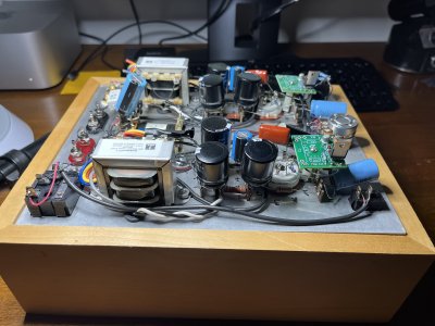
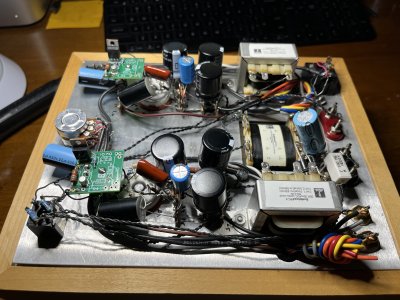
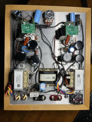
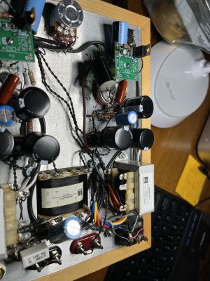
If at all possible, I'd post some photos of your build as it sits now, as that will give us an idea of which kit you have, and there may be a part that's visibly upset.  It would also be a good idea to do a voltage check to see if anything is obviously awry.
 
Here are some photos. I don't know where my original manuals are, so not sure where I can find the version needed for the SEX kit I have to check voltages, etc.
 

Attachments

  • IMG_6030.jpg
    IMG_6030.jpg
    3.7 MB · Views: 11
  • IMG_6031.jpg
    IMG_6031.jpg
    3.6 MB · Views: 9
  • IMG_6032.jpg
    IMG_6032.jpg
    3.8 MB · Views: 11
  • IMG_6033.jpg
    IMG_6033.jpg
    3.5 MB · Views: 6
That's a SEX 2.0 with the C4S upgrade. 

Measuring the DC voltages at pin 3 on each octal socket and the DC voltage on the metal tab of Q2 on each C4S board will give a reasonable amount of information about how the amp is operating.

It's very likely that you'll need to hook the amp up to some cheap speakers and run it inverted in its base so you can poke around with a wooden chopstick, listening for an area that makes noise when you poke it, which is useful for directing resoldering efforts. 
 
I pocked around with a chopstick on all connections and heard no audible changes while poking around.

I'm not sure what you mean by pin 3 on octal socket, as that is ground? From octal pin 3 to ground on plug, it is 0V

Right Channel (A)
Q2 on C4S - 310.1 V

Left Channel (B)
Q2 on C4S - 315.9
 
Oh, and I found my old CD with manual, but no longer have a CD player to access the files. The label on the CD says the Rev 6-29-06, is it possible to get a digital copy of this PDF?
 
pevelg@gmail.com said:
From octal pin 3 to ground on plug, it is 0V

Right Channel (A)
Q2 on C4S - 310.1 V

Left Channel (B)
Q2 on C4S - 315.9
Yeah I'm forgetting that this kit has the autoformer output and the back bias arrangement.  Can you check the DC voltages at pin 4 on each tube as well?

The 300V on the metal tab of Q1 would not be great, just to be clear this is the bigger transistor that's an MJE5731A, not the little metal encapsulated 2N2907.  300V on the metal can of each 2N2907 isn't abnormal, but 300V on the metal tab of both MJE5731As would mean the amp couldn't really make much in the way of sound.
 
Ah, I forgot that Q ment transistor, I measured the voltage at the resistor lead near the Q2 marker (the 300V measurement). Let's try this again.

Right Channel (A)
Q2 Tab on C4S - 92.3 V
Octal Pin 3 - 0 V
Octal Pin 4 - 0 V

Left Channel (B)
Q2 Tab on C4S - 75.9 V
Octal Pin 3 - 0 V
Octal Pin 4 - 0 V

When measuring Octal Pin 4, I can "hear" the measurement through the headphone output, depending on setting of volume knob.
 
The third time is the charm, let's see pin 1 on each tube.

Your metal tab measurements are mostly good, could you let me know what your voltages are on pin 6 of each socket as well?
 
Right Channel (A)
Octal Pin 1: -17.47 V
Octal Pin 6:  2.674 V

Left Channel (B)
Octal Pin 1: -16.94 V
Octal Pin 6:  2.284 V
 
The voltages I am reading now (with tubes switched) are:

Right Channel (A)
Octal Pin 6:  ~2.654 V

Left Channel (B)
Octal Pin 6:  2.283 V

On channel A (right), the voltage started around 2.7 and was slowly going down by 1 mV every few seconds or so, down to 2.654 after a few minutes. The left channel (B), was much more stable, staying within a few mV or the original value.
 
On the little C4S boards, there's an I, O, and G terminal.  Could you let me know what the I terminal is on each side after the voltages are stabilized?
 
I'd reflow the solder joints on the C4S board on the A side, though don't reflow the ones for the LEDs.  You could also verify that the cathode resistor value is the same between halves, which would be the DC resistance between ground and pin 3. 
 
I reflowed all the joints (minus LEDs) on the A C4S. Since I lifted the C4S off the post to do this, I also reflowed all the pins on the octal plug. No difference in voltage measurements and the right channel continues to be noisy.

Do you mean pin 4, as three is ground? For these measurements, the GND probe was at GND bolt near plug.

A/Right:
R Pin3-GND: 0.2 ohm
R Pin4-GND: 7.3 k ohm

B/Left:
R Pin3-GND: 0.2 ohm
R Pin4-GND: 7.6 k ohm

I measured the other pins as well, and the resistance is approximately the same between A/B for all pins.
 
Sorry, should be pin 6.  The arrangement of the big half and the small half in the 6DN7 is hard to keep straight in my head.
 
For resistance measurements, should the amp be plugged in and on or unplugged and off?

If off, the values are:

A:
R Pin 6 - 1.27 k ohm
R Pin 4 - 1.3k ohm

B:
R Pin 6 - 1.27 k ohm
R Pin 4 - 2..05k ohm
 
Back
Top