No Sound from Rt Channel after Speedball Upgrade

cfschill

New member
Greetings! I'm hoping you can help. I started with a working Crack, and here's what I have after the Speedball install & check:

-All LEDs light up
-OA measures a little over at ~115V
-OB measures in at ~130V
-G is good at 0
-B+ is good at 192V
-Both tubes glow
-Fuse is good
-Music only out of left side; switched inputs & same (no sound from rt side)

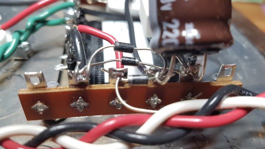
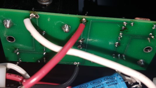
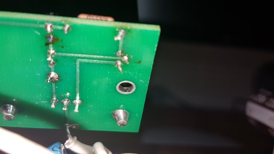
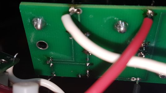
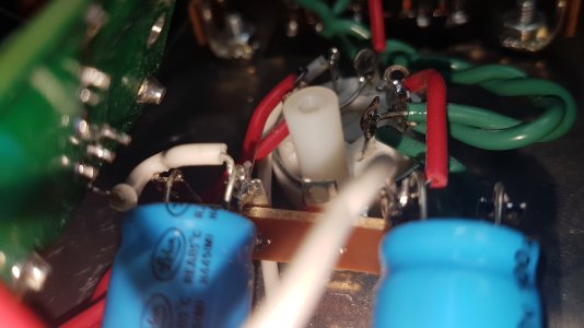
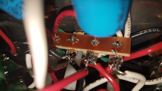
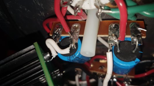
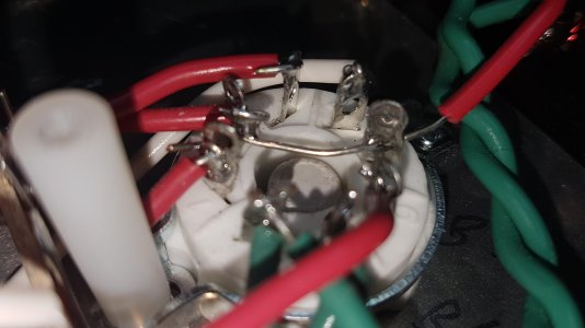
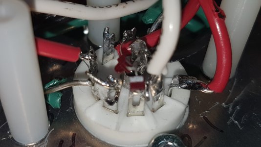
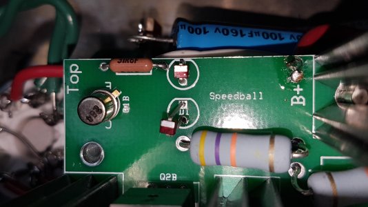
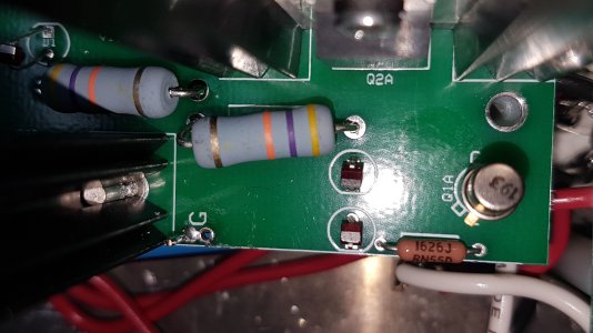
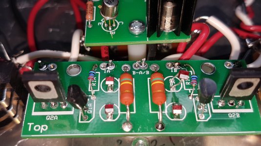
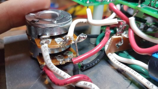
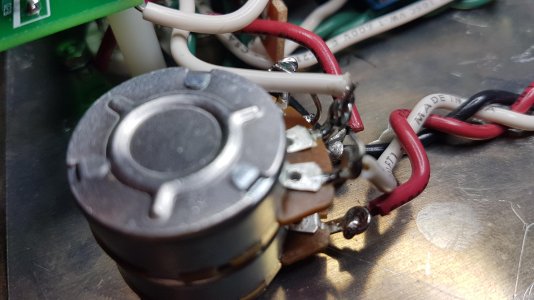
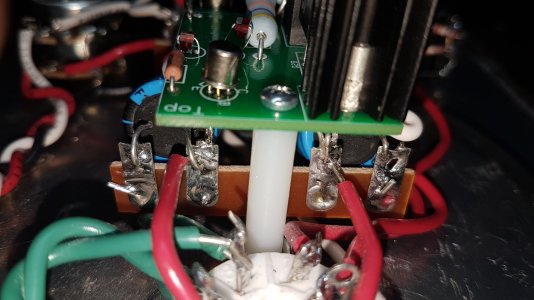
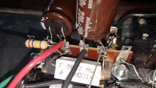
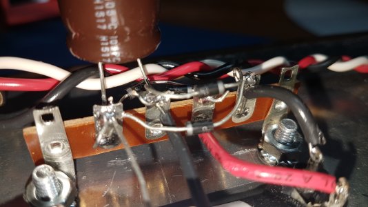
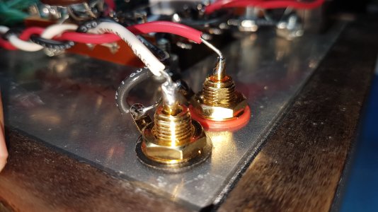
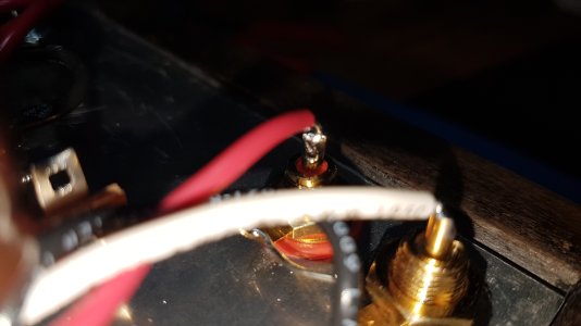
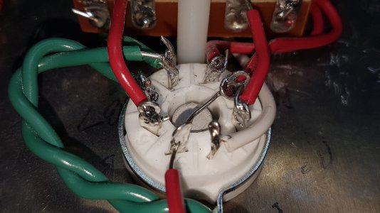
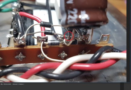
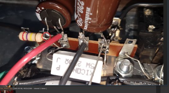
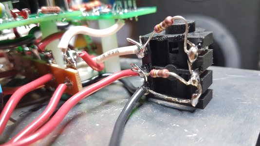
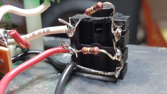
All components appear to be in their proper orientation, I've redone all solder connections at the two boards, and nothing changed (still no sound from the rt side).  I haven't tried resoldering the wires that bridge the boards yet.. that's the next step, and the only other that it could be, unless a component has gone bad.  Please chime in if you have any suggestions &/or need more information. 
 
Resoldered all the wired connections from 3U, 4U, 7U & 9U, as well as the right channel input, and now getting a slight sound from the right channel.  When I remove the left channel, I can barely hear the right channel input, and it comes through both sides of my headphones.  And not a full signal either.. low volume & kind of intermittent/gargley.  I get the same when I switch the RCA feeds, so the problem is definitely on the Crack/Speedball side of the equation.

When I switch RCA feeds to the left channel input, all comes through strong & proper out the left channel of the headphones.

Still fishing for thoughts/suggestions, hoping someone can help.
 
How are the voltages on the front board? 

Your voltages on the big PC board aren't really indicative of anything not working.  I suspect there is an issue outside of the Speedball itself here, and you've disturbed it during the installation.  Sometimes it can really help to post photos of your build, as we may be able to spot the culprit.

-PB
 
Sorry -- left out the other board info.  Front board check:

-OA = 82V
-IA = 193V
-B-A/B = 0V
-IB = 194V
-OB = 84V

All seems within good ranges on the front board.  I can post some photos.  Any areas in particular?
 
The only area that isn't of strong interest is the wiring that sits on the 6 lug strips on the power transformer.  Everything else is fair game as a possibility for creating a problem like the one you're having.
 
Tough getting good photos with my smartphone w/o taking more apart.  Please let me know if it will help you to get more photos in certain areas. 

First time project, so I know there is plenty room for improvement on the soldering, but again: the Crack was working flawlessly before I added the Speedball upgrade, though I agree with your suspicion that it's likely an issue outside the Speedball.

I hope these help.  THANK YOU for your assistance.. I really appreciate it.
 

Attachments

  • 20170708_204025.jpg
    20170708_204025.jpg
    2.9 MB · Views: 28
  • 20170708_204804.jpg
    20170708_204804.jpg
    2.3 MB · Views: 17
  • 20170708_204812.jpg
    20170708_204812.jpg
    2.1 MB · Views: 15
  • 20170708_204821.jpg
    20170708_204821.jpg
    1.9 MB · Views: 16
  • 20170708_204856.jpg
    20170708_204856.jpg
    2.6 MB · Views: 18
  • 20170708_204928.jpg
    20170708_204928.jpg
    2.5 MB · Views: 16
  • 20170708_204943.jpg
    20170708_204943.jpg
    776 KB · Views: 16
  • 20170708_205009.jpg
    20170708_205009.jpg
    646.9 KB · Views: 16
  • 20170708_205039.jpg
    20170708_205039.jpg
    2 MB · Views: 22
  • 20170708_204730.jpg
    20170708_204730.jpg
    781.1 KB · Views: 14
  • 20170708_204715.jpg
    20170708_204715.jpg
    2.5 MB · Views: 17
  • 20170708_204601.jpg
    20170708_204601.jpg
    2.7 MB · Views: 22
  • 20170708_204110.jpg
    20170708_204110.jpg
    3.2 MB · Views: 28
  • 20170708_204147.jpg
    20170708_204147.jpg
    818.7 KB · Views: 20
  • 20170708_204256.jpg
    20170708_204256.jpg
    3 MB · Views: 26
  • 20170708_204333.jpg
    20170708_204333.jpg
    2.9 MB · Views: 18
  • 20170708_204351.jpg
    20170708_204351.jpg
    2.9 MB · Views: 19
  • 20170708_204416.jpg
    20170708_204416.jpg
    3 MB · Views: 21
  • 20170708_204427.jpg
    20170708_204427.jpg
    2.3 MB · Views: 16
  • 20170708_204512.jpg
    20170708_204512.jpg
    2.5 MB · Views: 22
Here are a couple of potentially critical areas to touch up.  If the leads/terminals in the red circles touch, you short out the high voltage power supply.

Are you, by chance, using lead free solder?  (you may see the word "bearing" on the spool label)  Also, how much power does your soldering iron/station put out?

I see plenty of solder joints that don't have adequate heat applied, and I'd bet that one of them is causing the problem you're experiencing.  Cold solder joints also don't sound so good.

There's also some potential for issues with flaky joints on the headphone jack, which isn't pictured.

Once we have confirmed that you have some decent solder with lead in it and an iron that's rated for at least 40W, then I would go ahead and reheat all the solder joints in the amp and add just a little bit of additional solder to each.  I would also hit the joints on the PC boards, as some of them look like they could use a little additional heat.

-PB
 

Attachments

  • crack1.jpg
    crack1.jpg
    261.2 KB · Views: 52
  • crack2.jpg
    crack2.jpg
    331.3 KB · Views: 47
Caucasian Blackplate said:
Are you, by chance, using lead free solder?  (you may see the word "bearing" on the spool label)  Also, how much power does your soldering iron/station put out?

I see plenty of solder joints that don't have adequate heat applied, and I'd bet that one of them is causing the problem you're experiencing.  Cold solder joints also don't sound so good.

There's also some potential for issues with flaky joints on the headphone jack, which isn't pictured.

Once we have confirmed that you have some decent solder with lead in it and an iron that's rated for at least 40W, then I would go ahead and reheat all the solder joints in the amp and add just a little bit of additional solder to each.  I would also hit the joints on the PC boards, as some of them look like they could use a little additional heat.

Advice taken and I'll have at it tonight.  The solder I have is a 2% rosin core, 60/40 tin/lead mix.  The gun/station is an entry-level Weller WLC100 40-Watt station, that's adjustable.  I've been conservatively soldering at the 3 mark (on a 5 scale), as I've read how some electrical components can change value if heated too much.  I'll bump it up to a 4 and resolder all the joints, and supplement with additional solder, as suggested.  Thanks again PB.  Fingers crossed...
 
Ok... no bumps to 11, nor 5 for that matter.  4 seemed to be plenty to get me quick, happy little shiney joints that seated into the pots quite nicely.  I went through all of the joints... all of them -- re-heated at minimum, added a little solder if it looked like it needed it, wicked away excess than re-soldered for all other joints.  Then, with a bit of excited anticipation, plugged everything in.. and... low and behold... the same.

<scratches head>

Then I played with the headphone jack's seating position.  Not sure if it helps to narrow my issue, but if I sink the jack about half to two-thirds the way down, it plays from both sides of the headphones.  Not sure if it's a monaural signal or stereo to both, or if I'm actually on to something here.. Any thoughts?
 
That does not indicate anything except that both the tip and ring of the plug are in contact with the working channel of the jack at the same time, because the plug is not pushed in all the way.
 
The next step is to download a 60Hz tone that you can play into the Crack.  When I do this, I use a frequency generator on my phone set to sine wave and as close to 60Hz as it'll go, and the volume all the way up. 

With that tone playing into your Crack, set your meter to AC volts (on a 2V scale if your meter isn't autoranging), then measure the AC voltage from ground to the center pin on each RCA jack and report that value back here.  The amp doesn't need to be on for this test.

-PB
 
I'll do the 60Hz test & report back.  I took a couple photos of the jack soldering in the interim:
 

Attachments

  • 20170711_160245.jpg
    20170711_160245.jpg
    845.5 KB · Views: 49
  • 20170711_160311.jpg
    20170711_160311.jpg
    2.6 MB · Views: 35
Caucasian Blackplate said:
The next step is to download a 60Hz tone that you can play into the Crack.  When I do this, I use a frequency generator on my phone set to sine wave and as close to 60Hz as it'll go, and the volume all the way up. 

With that tone playing into your Crack, set your meter to AC volts (on a 2V scale if your meter isn't autoranging), then measure the AC voltage from ground to the center pin on each RCA jack and report that value back here.  The amp doesn't need to be on for this test.

Ok.. Did exactly this & the voltage varied, based on where the preamp volume was set at, naturally.  At the lower end, we were at about 0.3, both sides, and full/max measured 4.1 volts at both inputs.  Thank you for your continued help.  I appreciate it.
 
Woah, 4V at full volume?  That'll be great for these tests!

The next step is to measure the AC voltage between ground and pin 2 on the 9 pin socket, then pin 7 on the 9 pin socket.  These are tough measurements to take, but the amp should be off for this testing anyway and the volume pot on the Crack should be all the way up.

We'll keep working our way through the circuit tracing this 60Hz tone. 

-PB
 
Caucasian Blackplate said:
The next step is to measure the AC voltage between ground and pin 2 on the 9 pin socket, then pin 7 on the 9 pin socket.  These are tough measurements to take, but the amp should be off for this testing anyway and the volume pot on the Crack should be all the way up.
I randomly get a chunk of time to work through the steps; please forgive the delays.  At first I measured with the tubes in and noted zero measurements.  Then guessed you must have meant with the 9-pin tube removed & noted:

=> 0.8V across ground and pin 2
=> 0.0V across ground and pin 7

Looking forward to the next step in solving this riddle.  As always, I appreciate your expertise.. THANK YOU.
 
The AC voltage should be present with or without the 12AU7 installed.

With the volume pot all the way up, getting 0.8V at A2 and 0V at A7 means that the signal voltage isn't making it to the 9 pin socket properly.  This could be because something is touching A7 that shouldn't be, because two lugs on the pot are shorted, or perhaps there's a broken or poorly soldered wire.

The Speedball itself won't cause a problem like this.

-PB
 
OK.  I am now at 4.2V, both pins A2 & A7, with the volume pot all the way up on both the pre-amp & headphone amp.  What's the next plan of action, o captain my captain?
 
Did you end up needing to do anything to get 4.2V at pin A2?

The next test is to turn the amp on and measure the AC voltage at terminals 6 and 10 with a pair of headphones connected (always use a spare pair of inexpensive headphones for testing) and the volume about 1/4 of the way up.

-PB
 
Back
Top