new build problems

pogue

New member
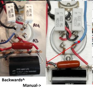
resistance reading checked out. follow dc voltage checks was from ac outlet measuring 122volts.any value not list was good.
hv+ 434v  1- 429v  2-433v  6-0v  11-0v  12- 425v  14-425v  15-426v  16-0v  17-425v  19-426  20-0v

a1-006v  a2-425v  a3-0  a4-006v  c1-0v  c2-425v  c3-425v  c4-0v

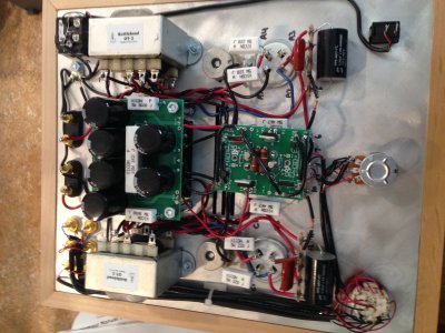
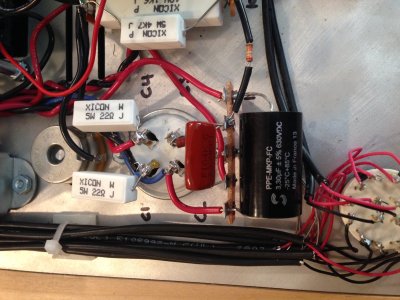
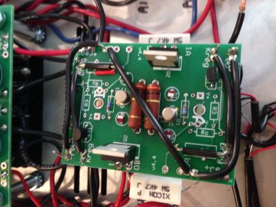
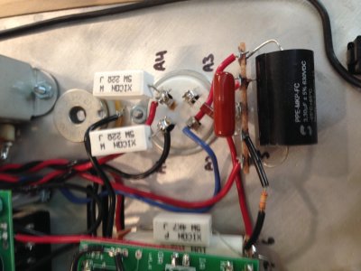
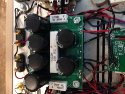
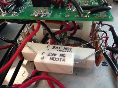
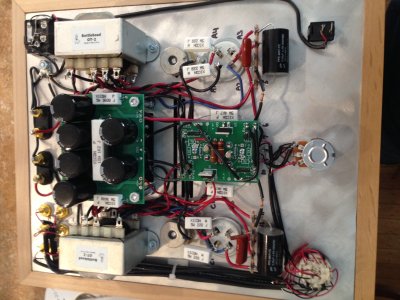
I'VE POSTED A FEW PIC.'S EXCUSE THE MESSY WORK.  THANKS FOR ALL THE HELP
 

Attachments

  • IMG_0595.JPG
    IMG_0595.JPG
    648.6 KB · Views: 175
  • IMG_0596.JPG
    IMG_0596.JPG
    688.7 KB · Views: 134
  • IMG_0597.JPG
    IMG_0597.JPG
    612.9 KB · Views: 117
  • IMG_0598-1.JPG
    IMG_0598-1.JPG
    476.7 KB · Views: 126
  • IMG_0599.JPG
    IMG_0599.JPG
    522.4 KB · Views: 100
  • IMG_0600-1.JPG
    IMG_0600-1.JPG
    566.6 KB · Views: 121
  • IMG_0601.JPG
    IMG_0601.JPG
    646 KB · Views: 139
You may have to adjust some wire lengths with the top plate flipped.  This may/may not create some hum issues.  Avoid obvious trouble and you should bo ok.
 
Does the tube that won't glow function in the other channel?

Neither 2A3 is drawing any current, and resolving this may be quite complicated by the flipped layout. 

On one of your hum pots, the black wire in the center needs to be trimmed, as it is awfully close to touching the plate.  If it touches the plate, and you let the amp run, you will burn up your plate choke on that channel.
 
i will flip the tubes around and trim the black wire. i wired the amp as per the instructions, i'm thinking that the channels has just flip flopped? all wire lengths are as per thee instructions also or has flip flopping caused bigger problems.  thanks paul
 
While everything looks odd being a mirror image of the regular build, to me A2/A3 and C2/C3 seem right. But I may be mistaken.
 
You can flip the plate, but you can't  flip the tube.  Viewing from the bottom with the transformer top, A1 should be at about one o'clock and be numbered clockwise with A4 ending up around 11 o'clock.  See page 42 in the manual.  Yours appear to be numbered from 11 o'clock counterclockwise to 1 o'clock.

 
borism said:
While everything looks odd being a mirror image of the regular build, to me A2/A3 and C2/C3 seem right. But I may be mistaken.
It can be tough when things are mirrored, as I believe our brains may want to mirror everything, which ends up causing such problems.
 

Attachments

  • IMG_0598-1.JPG
    IMG_0598-1.JPG
    381.4 KB · Views: 209
THANK YOU FOR EVERYONES HELP. I FIX THE WIRING ON THE TUBE SOCKETS AND NOW HAVE A FEW NEW READINGS.
#2 - 393V                  A1 - 53V,  A4- 53V
#5 - 51V                    0A - 380V,  0B - 380V
#6 - 0                          KREG - 0V BOTH SIDES
#14 - 392V
ALL THE WIRING EXECPT FOR THE TUBE SOCKETS IS THE SAME AS THE PICTURES. 
THANKS 
 
Well, of course any mirrored mis-wiring of the 9-pin socket would be a likely explanation. If it is correctly wired, then a failure of the tube heater to light up would be a likely (and easily checked) test.
 
ok thanks for all the help so far. all tubes are working and all the testing checks out except for two values.  #5 reads 60volts and #11 reads 0volts. have checked the manual and everything looks good, my only concern would be the 1.6k ohm and 47 ohm resistors. could they cause this problem. thanks paul 
 
Back
Top