PassionForSound
New member
Hi all,
A friend of mine has asked me to install an attenuator in his SEX, but it came with no hookup instructions so I'm working blind. I've taken some pics of the unit in question and hope you can help me work out how to wire it into the SEX.
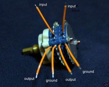
You can see in the images below that the attenuator has 2 layers of SMD resistors. It has a pair of solder tabs on one side (near labels for the ground and input) and a pair of solder tabs on the other side which are unlabelled.
I'm guessing that the solder tabs near the labels are for the ground while the unlabelled tabs are the output, but I'm hoping to gain confirmation of this and am also left wondering where the input wires connect. Should they connect to the solder pads of the resistors directly above the "IN" labels?


A friend of mine has asked me to install an attenuator in his SEX, but it came with no hookup instructions so I'm working blind. I've taken some pics of the unit in question and hope you can help me work out how to wire it into the SEX.
You can see in the images below that the attenuator has 2 layers of SMD resistors. It has a pair of solder tabs on one side (near labels for the ground and input) and a pair of solder tabs on the other side which are unlabelled.
I'm guessing that the solder tabs near the labels are for the ground while the unlabelled tabs are the output, but I'm hoping to gain confirmation of this and am also left wondering where the input wires connect. Should they connect to the solder pads of the resistors directly above the "IN" labels?