Tarquinflimbim
New member
- for future readers - make sure you fit all the valves before doing the tests on page 73. Doh!
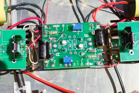
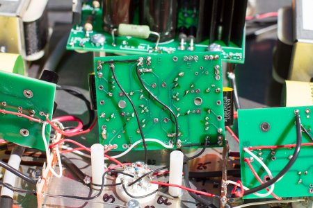
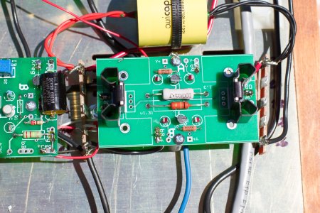
So to follow protocol - here is the description: Resistances check out fine. Terminal Voltage (DC)
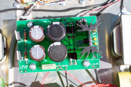
+275vDC on the Power Supply Board 275V - Mine - 295V
+6.3vDC on the Power Supply Board 6.3V - Mine 6.29V
IA on the A side C4S Board 275V - Mine 290V
IA on the B side C4S Board 275V - Mine 290V
Breg Regulator Board (both sides) 220V - Mine 220V
-reg Regulator Board (both sides) 0V - Mine 0 or nearly 0
Kreg Regulator Board (both sides) 8-12V - Mine 4.3V and 3.8V
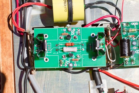
Both A side LED's are lit on both C4S boards, both B side LED's are dark.
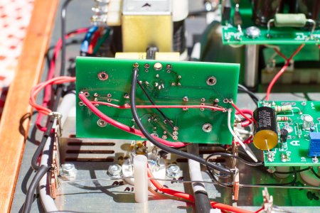
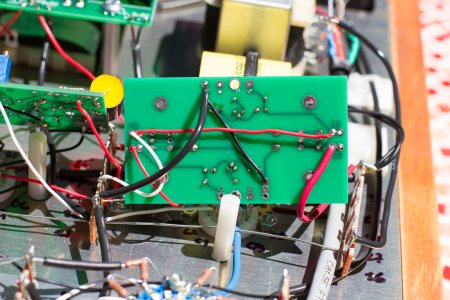
I resoldered the middle board (BIAS regulator board) and confirmed that I had connected the legs together on the adjustment pot.
I have removed the central board three times now, so I'm beginning to think my error may be elsewhere! Any help appreciated.
Tarquin Flimbim.
So to follow protocol - here is the description: Resistances check out fine. Terminal Voltage (DC)
+275vDC on the Power Supply Board 275V - Mine - 295V
+6.3vDC on the Power Supply Board 6.3V - Mine 6.29V
IA on the A side C4S Board 275V - Mine 290V
IA on the B side C4S Board 275V - Mine 290V
Breg Regulator Board (both sides) 220V - Mine 220V
-reg Regulator Board (both sides) 0V - Mine 0 or nearly 0
Kreg Regulator Board (both sides) 8-12V - Mine 4.3V and 3.8V
Both A side LED's are lit on both C4S boards, both B side LED's are dark.
I resoldered the middle board (BIAS regulator board) and confirmed that I had connected the legs together on the adjustment pot.
I have removed the central board three times now, so I'm beginning to think my error may be elsewhere! Any help appreciated.
Tarquin Flimbim.