You are using an out of date browser. It may not display this or other websites correctly.
You should upgrade or use an alternative browser.
You should upgrade or use an alternative browser.
Mainline Questions
- Thread starter Tabaia
- Start date
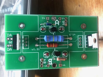
Resistors are not directional.
")
The second way is more correct than the first, but both would work.
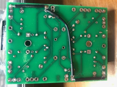
You can post them here. So far, I'd suggest either turning the iron temp up all the way or holding on the joints a little longer so they flow out a bit more.
Hi Paul,
Here are the pictures.
Thanks for your support
Here are the pictures.
Thanks for your support
Attachments


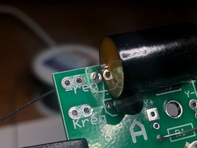
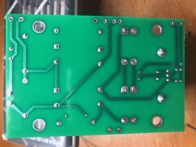
Definitely more heat is needed, and a tiny bit of extra solder.
Yes, when you get the solder hot enough, it will suck into the board a bit.
https://www.youtube.com/watch?v=EN16Pi7pcfk
https://www.youtube.com/watch?v=EN16Pi7pcfk
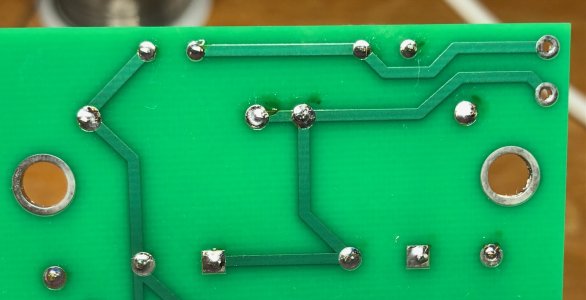
I'd leave your iron on those joints a bit longer.
Hi Paul,
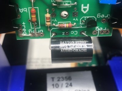
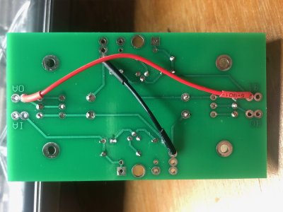
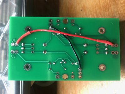
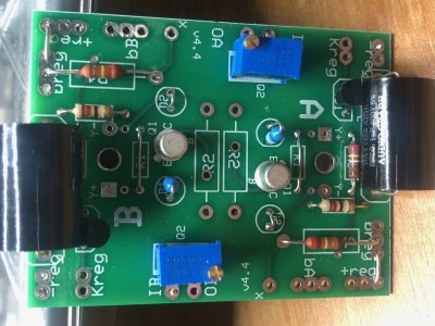
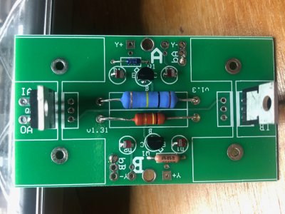
I have done a fair bit of reworking and I think it might be good now,
Would you kindly have a look over the solder as well as the component placement.
I think is all correct however since i'm a first timer it would be great to have it looked over by someone in the know.
Looking forward to your response
Many thanks Tunji
Attachments
-
 IMG_6269.JPG583.4 KB · Views: 3
 -
 IMG_6268.jpg565.4 KB · Views: 2
 -
 IMG_6267.jpg544.4 KB · Views: 3
 -
 IMG_6266.jpg552.7 KB · Views: 1
 -
 IMG_6265.jpg480.3 KB · Views: 4
 -
 IMG_6264.jpg465.1 KB · Views: 0
 -
 IMG_6263.jpg385.5 KB · Views: 3
 -
 IMG_6262.jpg570.1 KB · Views: 1
 -
 IMG_6261.jpg487.5 KB · Views: 6
 -
 IMG_6270.jpg631.4 KB · Views: 1
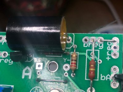
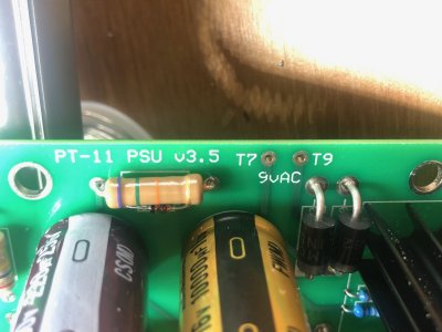
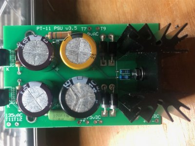
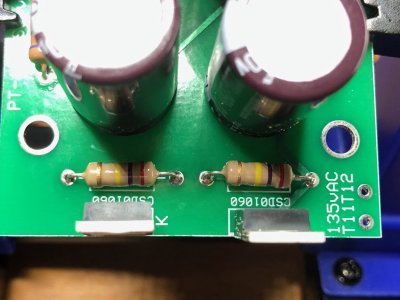
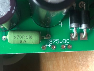
The 1N5820s and the 5W resistor have not been heated enough to be properly soldered.
https://www.youtube.com/watch?v=EN16Pi7pcfk
https://www.youtube.com/watch?v=EN16Pi7pcfk
Similar threads
- Replies
- 3
- Views
- 155