Mainline BIAS Issue

Mike V.

New member
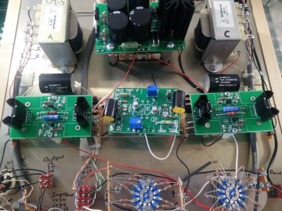
Hi guys, long time no chat, Finally I´ve dicided to build my Mainline kit that I bought in Dec'14. I have completed the kit, all messurements were correct, the 275V is 300V in my Reading. the rest of ohms and volts are perfect.

The issue I got is adjusting the BIAS of the A side. The B side I set it at 145V, but the A side is stucked at 80V if I rotate the switch I can get up to 81 or down to 74V until I start listening a click every turn I do. I switched the tubes and I was able to set BIAS at the B side at 145V, but The up I could get on the A side with the other tuve was 97V.

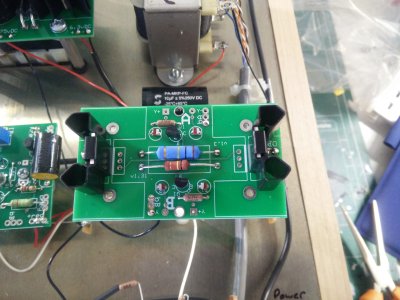
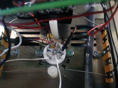
I have inspected all the soldering joints, and look fine, all leds are lighting. the only issue I guess I have is one Capacitor ZU5 that I solded it to close to its body.

Please help me!

 
OB on the center board is the adjustable bias voltage for the A side.  What voltage do you have on OB at each end of the trimmer pot rotation? 
 
Sorry the side that I don't get the correct bias is the one of the C socket.

The OA measurements are the following: 3.7v - 0.69v
 
I have checked and compare all voltages from both C4S boards, and all are equal except the one related to the bias 145v - 96v. I guess that will take me to the tube socket and after I have resolder everything, maybe the problems is with a ZU5 or a 1/8w resistor that I have blown  or is defective?
 
Caucasian Blackplate said:
OB on the center board is the adjustable bias voltage for the A side.  What voltage do you have on OB at each end of the trimmer pot rotation?

Paul,
any thoughts on where might be the issue?
 
Can you verify that the resistance across the trim pot is actually changing when you turn the trim screw?
 
Doc B. said:
Can you verify that the resistance across the trim pot is actually changing when you turn the trim screw?

Doc, How can I do that, do I messure the ohms from one leg of the trim to an other? the amp needs to be turn on?
 
Yes, from one end pin to the other end pin on the pot. Power off and amp unplugged as you are measuring resistance, not voltage.
 
Photos would be helpful at this point.  Can you confirm that you get the same adjustable range of voltages (approximately) from OB and OA on the center PC board?

If so, but your plate voltage won't move, this suggests a miswire or shorted connections, most likely on the bottom of the high current C4S board on the offending side.
 
Doc B. said:
Yes, from one end pin to the other end pin on the pot. Power off and amp unplugged as you are measuring resistance, not voltage.

Doc, The resistance values are from 1 ohm to 2kohm
 
These are the 3 boards


Attachments

  • 14677520192841512176228.jpg
    14677520192841512176228.jpg
    5.1 MB · Views: 87
  • 1467752559885-577035665.jpg
    1467752559885-577035665.jpg
    4.6 MB · Views: 69
  • 146775257868224085675.jpg
    146775257868224085675.jpg
    4.3 MB · Views: 74
  • 1467752600560-1558684613.jpg
    1467752600560-1558684613.jpg
    3.8 MB · Views: 68
  • 1467752617899-1983717712.jpg
    1467752617899-1983717712.jpg
    4 MB · Views: 71
Doc B. said:
Could you send a pic of the underside of the middle board?
 

Attachments

  • 1467752805907-253187952.jpg
    1467752805907-253187952.jpg
    4.2 MB · Views: 65
  • 1467752836948-1536690387.jpg
    1467752836948-1536690387.jpg
    4.1 MB · Views: 58
  • 1467752924998331310151.jpg
    1467752924998331310151.jpg
    4.4 MB · Views: 77
Caucasian Blackplate said:
Photos would be helpful at this point.  Can you confirm that you get the same adjustable range of voltages (approximately) from OB and OA on the center PC board?

If so, but your plate voltage won't move, this suggests a miswire or shorted connections, most likely on the bottom of the high current C4S board on the offending side.

Yes I get the same. Tonight I will check the C4S board and check if everything is soldered as the manual.
 
On C side, you have resistors from the center lug going to 3 and 8 of the tube socket. This is supposed to be 2 and 8.

Cheers,
Mischa
 
swich401 said:
On C side, you have resistors from the center lug going to 3 and 8 of the tube socket. This is supposed to be 2 and 8.

Cheers,
Mischa

I knew the issue was down there! But couldn't find where, That's the problem of building an amp at late night hours.

That for sure resolved the Bias issue. Thanks!

The final result a clean pure delightful sound!
 
Doc, Paul, Mischa,

Thanks for your help! A tired eye is a dangerous thing lol hopefully all my soldering was clean and well done. Got a clean sound.

Delightful sound!
 
I would also resolder the middle leg of the MJE5731A on the "A" side, as it looks like the flux hasn't flowed out of the joint completely.

-PB
 
Back
Top