Lost left channel on my Reduction

cpditter

New member
Hi:
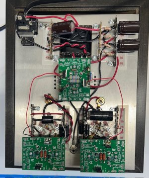
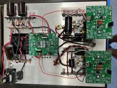
Fired up my system to play some vinyl  last night after being gone for a couple of weeks.  Other sources (CD, Streamer) fine so suspected it was my Reduction phono preamp.

Tried swapping tubes but no change, so not a bad tube.  Also swapped out to a diff turntable and cables to eliminate that variable.  Finally, I also put a different phono preamp into the system and all worked.  So seems to be the Reduction based on all that.

Took a look on the workbench and cannot find any obvious bad solder joints or loose wires...so I'm at a loss as to how to proceed.  My electrical knowledge is scant...I can follow directions and solder and use multi-meter...so love building the kits but beyond that I'm limited... :-\

Would really appreciate some tech support help...

Regards,
Chuck

p.s. My kit has the added Integration upgrade...
 
Could you post the OA and OB voltages on the green C4S boards up in the front of the chassis?  That will tell us a lot about what's going on.  Are the LEDs on the tube sockets all lit?  (if one is out, resist the urge to resolder it for now)
 
Thanks for the reply!  Sorry for the delay responding, we had a commitment today...

The LED between pins B8 and B9 is not lit.  Neither are the two LED's on the B-side of the integration boards (if that is the correct way to refer to them).  All others are on.

Sorry for my ignorance but can you tell me where to measure the OA and OB voltage?

Chuck
 
You would want to revisit the Integration manual, which is a bit more specific about this.  You'll need to set your meter to DC voltage, put the black probe into the ground post, then test the voltages at OA and OB with the red probe.
 
OK will do.

I have to leave on a business trip tomorrow a.m. so will likely be a few days before i respond with the voltages...thank you.
Chuck
 
HI:

Finally back from trip and have some measurements.

Terminal 82:  68v
Terminal 18:  66v
Terminal 26:  71v
Terminal 31:  18.3v  (Was 67v when I originally finished the build)

Also, Terminal 31 is on the side where two of the led's are not lit...
 
More pics
 

Attachments

  • IMG_2064.jpg
    IMG_2064.jpg
    250.6 KB · Views: 3
  • IMG_2062.jpg
    IMG_2062.jpg
    214 KB · Views: 0
  • IMG_2061.jpg
    IMG_2061.jpg
    100 KB · Views: 0
  • IMG_2060.jpg
    IMG_2060.jpg
    140 KB · Views: 8
  • IMG_2058.jpg
    IMG_2058.jpg
    225.7 KB · Views: 1
  • IMG_2057.jpg
    IMG_2057.jpg
    138.2 KB · Views: 1
  • IMG_2056.jpg
    IMG_2056.jpg
    208.9 KB · Views: 4
Let me know if these are better, saved in higher resolution...
THANKS
 

Attachments

  • IMG_2066.jpg
    IMG_2066.jpg
    2.5 MB · Views: 7
  • IMG_2068.jpg
    IMG_2068.jpg
    2.6 MB · Views: 3
The solder on 31 looks a little suspect. 

The 8 lug terminal strips require a bit of heat to solder properly, and definitely use leaded rosin core solder for this work.
 
By pin 8 I believe you mean pin B8 on the tube socket?  It is reading 1.38v.  Also, if I did not note earlier, I noted the led attached to that pin is NOT lit.
 
I'd make sure that everything at B8/B9 is securely mounted and captured by solder.  The same goes for the resistor that lands at B9, and I'd be looking carefully at both ends. 
 
OK.  Nothing appears loose but will try resoldering those connections next.  Is it best to use desolder braid and then resolder?...or just reheat and add some more solder?

p.s.  We have house guests for a few days so may take a bit to get to and respond...thanks for sticking with me on this.

Chuck
 
I would not reflow any joints with LEDs connected to them unless they are obviously problematic.  For the other joints, you can just reheat the solder that's there, and add a tiny bit if it's absolutely necessary.
 
Back
Top