kill_surf_city
New member
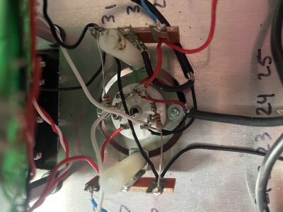
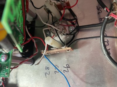
Paul Birkeland said:Can I see what the D socket looks like with that board pulled out? I do see one solder joint on one of the PN2907s that doesn't look 100%, but nothing else that's obvious.
sure thing. I'll reflow that PN2907 as well.