Large PCB voltage wrong and LED not lighting up

jlucky

New member
Hi all,
My crack has been functioning fine before the attempted upgrade.

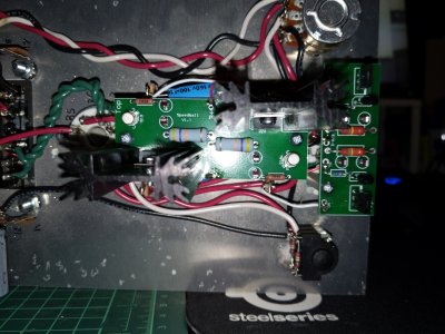
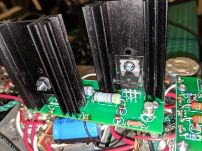
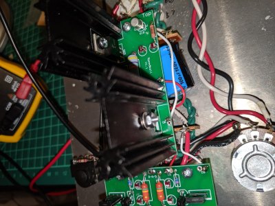
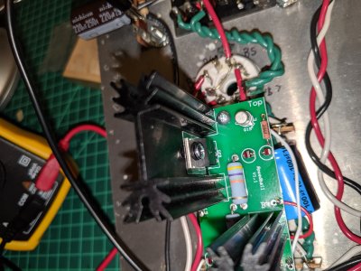
All resistance tests passed - Large PCB tests came back as over limit. LEDs on the small PCB and the tube connector below it are all good and glowing, but those on the large PCB aren't lighting up at all and my DC voltage measurements are all wrong too.
I'm in Australia, so mains power is approx. 220V
OB - 207V
G - 223
B+ - 95.5
OA - started near 178 and slowly ticked down to 150V

I'm pretty sure that there was no faulty soldering for the Large PCB.

Help?
 
jlucky said:
G is the ground connection, are you sure you have this connection wired to terminal 3?  If you do, then you almost certainly have a faulty solder joint on a ground wire in the original build (the black wires that go from the RCA jacks to the volume pot, to terminal 3, to the headphone jack, then back up through the power supply built above the power transformer)

-PB
 
Thanks Paul, I had mixed up which terminal was which. I have fixed that (as well as the red wire in T4 going to B+)
I am now getting the following voltages but still no glowing LEDs

ob 54.5v
g 1mv
b+ 94.3v
oa 180v
 
small pcb measurements

OA 53.5V
IA 91.5V
B-A/B 1mV
IB 90.85V
OB 72.85V

From what I can tell, OA, B-A/B and OB are all ok (OA's difference is minor, but it might be wrong) but I am greatly under voltage in IA and IB.
 
Can you check that the red wire for B+ of the large board is connected to the proper terminal?

53V on OA is what I would expect if you had a backwards PN2907 on the A side of your small C4S board, but that isn't the case from your photos. 
 
I have given the small PCB wiring a look over and it all seems right to me. White lead from 1u to OA, red lead from 2u toIA, black lead from 3u to B-A/B, red lead from 4u to IA, and white lead from 5u to OB.

Large PCB has white lead rom 7u to OB, white lead from 9u to OA, black lead from 3u to G and red lead from 4u to B+. Does it matter which of the two holes on each of the PCB parts is used?
 
I would recommend double checking the installation of your TIP50 transistors, and more specifically that the hardware is installed in the exact manner described in the manual.  The symptoms you're describing are consistent with a TIP50 metal tab that's making metal on metal contact with a heatsink, and this will cause damage to your Crack if it's run for very long.
 
Hi Paul,
I've had a look at the TIP50 transistor installation. I'm confident it's all as per the manual. There is no metal on metal between the transistor and the heat sink. The only metal on metal is the flat washer on the heat sink, but that is as per instructions. The shoulder washer on the screws is also the correct orientation.
 
What I would recommend doing is removing the big PC board and reheating all of the joints on it.  I would also loosen the hardware on each TIP50 and check to be sure that the black shoulder washer is situated so that the shoulder fits into the hole on the TIP50C.  When we see the B+ voltage drop to below 100V when someone has installed a Speedball, this is usually from an installation issue with these parts. 

When you have the big board out, you can just tack in the 3K resistors on top of the upper terminals to be sure that the basic build is still working well.  I would also post some photos of the bottom of your big PC board and the wire jumpers sticking up on your amp. 

The one area of concern on your large PC board is that the TIP50 transistors aren't well soldered, especially the middle legs. 
 
Back
Top