You are using an out of date browser. It may not display this or other websites correctly.
You should upgrade or use an alternative browser.
You should upgrade or use an alternative browser.
Kaiju Driver Boards
- Thread starter Tmielke
- Start date
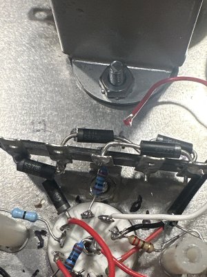
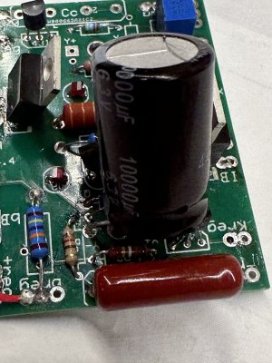
I'd be looking long and hard at the zener diodes mounted to the 5 lug terminal strip behind each 5670 socket. Those will determine the OA voltages before the 5670 warms up, and it looks like you may have some in backwards or have some that aren't properly installed.
I will go over that.I'd be looking long and hard at the zener diodes mounted to the 5 lug terminal strip behind each 5670 socket. Those will determine the OA voltages before the 5670 warms up, and it looks like you may have some in backwards or have some that aren't properly installed.
I built another driver boards with new components I received this past week.
It works fine on the d side
512v and 298v
All the diodes test good. The only variation from instructions was moonting the diode between 30 and 31 on the opposite side. It should work electrically.I will go over that.
I built another driver boards with new components I received this past week.
It works fine on the d side
512v and 298v
Does it look ok?
Attachments
All 9 pin socket connections need to go through the socket hole then bent up (and possibly around the top of the pin). If you go sideways with these connections, they can touch adjacent pins and blow things up.
Checked the clearance between pins with tube installed. There wasn't any issues but I did do a little trimming.All 9 pin socket connections need to go through the socket hole then bent up (and possibly around the top of the pin). If you go sideways with these connections, they can touch adjacent pins and blow things up.
I stripped the A side board of everything but the resistors. Checked all the resistors and there were no issues. I metered the transistors and regulators and they seemed ok. All voltage drops were very similar. As I have the ex board with a few new parts, I pulled the transistors and regulators from that one. If they are bad they all failed exactly the same on both boards.
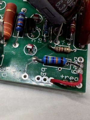
I reassembled the board being very mindful of my soldering and a closely inspected the finished product. No solder bridges.
Installed on A side and still have 159V at OA. Removed the working board from D side and installed the board from A side, still 159V at OA. Re-installed known good board on D side and it worked fine with 298V at OA.
My next thought is to order new transistors and regulators or I could just order another board kit. Thoughts?
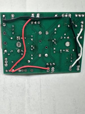
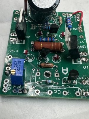
Can you show me the top and bottom of the offending board since you have it out?
It's worth double checking that the behavior is the same with both 5670 tubes. Beyond that, a fresh driver board and fresh zener diodes would be the approach that should yield rather assured success.
-PB
-PB
Received the fresh driver board kit. Built and installed all works as it should.It's worth double checking that the behavior is the same with both 5670 tubes. Beyond that, a fresh driver board and fresh zener diodes would be the approach that should yield rather assured success.
-PB
I did replace the zener diodes as well.
I also ordered the regulators and transistors to swap out on the current board. I swapped the components, installed the board and put the meter on OA prior to power up. When powered up OA jumped to 345v and then dropped, fairly quickly, to 158v. Any idea what would have caused this?
You didn't put them on a new board?
I tried on last time to get the original board to work by replacing transistors and regulators. I ordered these along with a complete driver board kit. I have some extras now.You didn't put them on a new board?
So with a completely new board and new components (including zener diodes), you're still having the same problem?
Ah, good!
Similar threads
- Replies
- 20
- Views
- 40K