Issues [resolved]

Markkr

New member
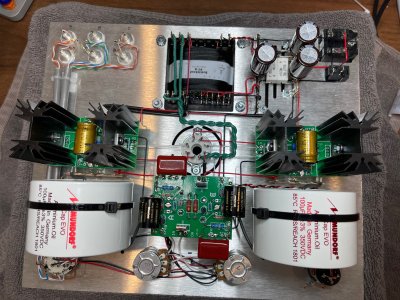
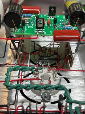
Well... I can certainly attest to the fact that this was a MUCH more difficult build than a regular Crack.

I was doing well all through the build, been going slow for 2 weeks now. All the preliminary tests passed just fine.

I finished up yesterday and now, the 6AQ5's no longer light... the voltages are all over the place. Oddly, when the 6AQ5's are in place, even the input voltage at the receptacle is very very low. Once I pull those tubes I get the expected 125v.

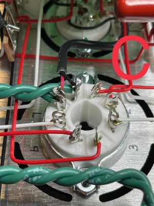
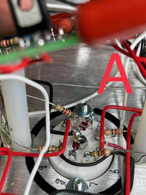
Additionally, during troubleshooting the center pin of the 6080 broke off and both of the 7 pin sockets are SUPER loose (I already spoke to Eileen and she shipped 2 replacement sockets)

okay, so man oh man... where do I begin? I have rechecked all 62 pages of documentation for errors.
 
Post build photos.

The 6AQ5s are lit by the STP wiring that feeds pins 3 and 4 on each 7 pin socket.  If you have a short in that wiring you could end up with many erroneous voltages.
 
Pics attached (and THANK YOU!)
 

Attachments

  • IMG_0027.jpg
    IMG_0027.jpg
    3.2 MB · Views: 47
  • IMG_0034.jpg
    IMG_0034.jpg
    3.6 MB · Views: 35
  • IMG_0035.jpg
    IMG_0035.jpg
    1.2 MB · Views: 19
  • IMG_0036.jpg
    IMG_0036.jpg
    1.6 MB · Views: 13
  • IMG_0037.jpg
    IMG_0037.jpg
    1.9 MB · Views: 25
I know I know... caps are supposed to wait until everything works, I was being impatient because they were so damn sexy on the bench
 
Yeah, the first thing I would do is to pull those caps out and put what we sent you in.  They are going to get in the way.
 
The second thing I would do is to pull out the piece of STP that's attached to the power transformer and replace it as we have it in the manual.  What you have done there may look cool, but the foil shield is nearly touching one of the lugs, and if it does you'll burn up your power transformer.
 
Will do on caps and STP.

6.76v AC between 15 and 9

(Just to be clear, I do not have any tubes plugged in at the moment)
 
This means your 6AQ5s are glowing, so this is inconsistent with the initial information you provided.  What are the IA/OA voltages on each big C4S board with the 6AQ5s in the sockets?
 
I promise there are no signs of glowing from either tube.

on the left side IA/OA are 0v DC

on the right side IA is1.6v DC and OA is .36v DC

Also: I just re-ran the "transformer secondary test" from the instructions and everything checks out fine.
 

Attachments

  • IMG_0045.jpg
    IMG_0045.jpg
    1.4 MB · Views: 16
Can you pop the big PC board off and show me the joints at B3/B4?  You almost have to have a wire there that's not captured by solder. Do the 6080 and 12AU7 glow? 

After we get all four tubes glowing, then we can go after why there's not really any DC voltage available for the circuit to run.

 
The 6080 and 12au7 glow just fine.

(With the amp powered off) I have successful continuity between PT8-15 and both sides of 3 and PT8-9 and both sides of 4 (just thinking maybe a break in the wire or something)

Could a tube be bad??

Also wanted to note, one of the 7 pin sockets is very very loose, when a tube is inserted its wobbly but the connection to the pins seems sufficient. (I did receive a new socket set in the mail today from Eileen but have not installed it yet)
 

Attachments

  • IMG_0046.jpg
    IMG_0046.jpg
    759.5 KB · Views: 16
  • IMG_0047.jpg
    IMG_0047.jpg
    740.2 KB · Views: 6
  • IMG_0048.jpg
    IMG_0048.jpg
    757.1 KB · Views: 9
  • IMG_0049.jpg
    IMG_0049.jpg
    692.6 KB · Views: 10
Could a tube be bad?  Sure, that's possible, but would both tubes be bad and not glow?  I would say that's nearly impossible. 

On the power transformer, I would heat up and remove the wires on 19 and 20 to take the HV supply completely out of the picture.  Next with just the 6AQ5 tubes plugged in, measure the AC voltage at pins 3 and 4 on each 7 pin socket.  There won't be DC voltage floating around, so this rather delicate measurement can be made with the big C4S boards unscrewed and laying off to the side.
 
In the picture you labeled "B" the black wire in the bottom right going to a terminal strip does not look soldered.  It has not been crimped to make the mechanical connection.  Also it looks like the wire has been pushed so far the insulation is in the terminal rather than the wire.  If that is true there is a very poor or no electrical connection.
 
"nearly impossible" is my middle. name  ;)

I disconnected 19 and 20... voltage on 3 & 4 on both sides is 6.5v AC

FWIW, the 6AQ5's glow now that 19 and 20 are removed
 
kgoss said:
In the picture you labeled "B" the black wire in the bottom right going to a terminal strip does not look soldered.  It has not been crimped to make the mechanical connection.  Also it looks like the wire has been pushed so far the insulation is in the terminal rather than the wire.  If that is true there is a very poor or no electrical connection.

I re-heated and secured that black wire just in case. Thanks for the feedback
 
Markkr said:
I disconnected 19 and 20... voltage on 3 & 4 on both sides is 6.5v AC

FWIW, the 6AQ5's glow now that 19 and 20 are removed
Disconnecting 19 and 20 does not make the 6AQ5s glow.  If you had 6+V AC on the transformer where the STP connects (I had you measure this), your 6AQ5s will glow.

There's a loose connection in the STP wiring from the transformers to pins 3/4 on the 7 pin sockets.  You'll need to find that before proceeding. 
 
Paul Birkeland said:
Disconnecting 19 and 20 does not make the 6AQ5s glow.  If you had 6+V AC on the transformer where the STP connects (I had you measure this), your 6AQ5s will glow.

There's a loose connection in the STP wiring from the transformers to pins 3/4 on the 7 pin sockets.  You'll need to find that before proceeding.

Will do, just so happens that I ordered a spare wiring kit for this amp, so I will just replace that STP with new pieces.
 
Back
Top