Integration Mod - Voltage test

Status
Not open for further replies.

Vili

New member
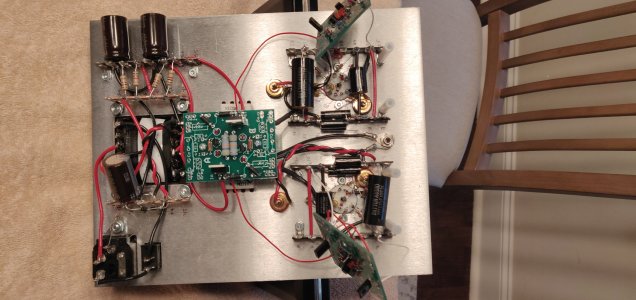
Reading DC voltage after second round of double check gives some erroneous values.
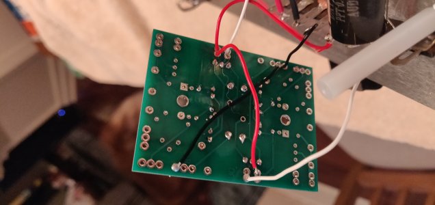
Voltage after 'Shunt Regulator Board' addition read slightly higher than 120VDC but was within ±10%.

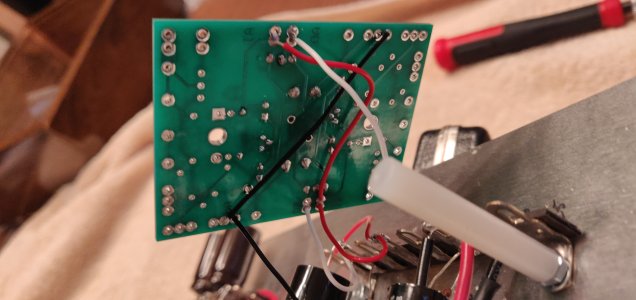
After integration of C4S is where it gets out of bed,
Reading on terminal 2 was 101 VDC.
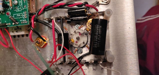
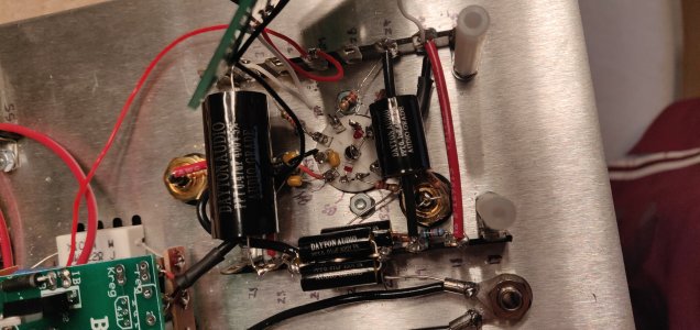
18, 26, and 31 were all within 2% of 74.4 VDC.

Only thing I can think of was after completion and testing of the default build, a few of the voltages were a little high, but only on one side of the assembly.
This didn't seem to effect balance between right and left channels at all, nor did it supply a distinctive difference in sound quality while playing (no noticeable hum)
 
Are all the LEDs lit up on the 9 pin sockets? 

There are two possibilities:

1.  The center leg of the MJE350 where you're getting 101V isn't well soldered.
2.  There's a loose connection in your build that you've moved and now you've lost one stage.

-PB
 
All LED's light up, but delayed and light only when the tube is fully illuminated.
I'll check the connection on the MJE350 and soldered/desoldered joints dealing with the integration addition.

I'll provide more info tomorrow afternoon.
 
Sorry for the many mods, was having some issues with file upload.

Please forgive terrible soldering, I'm really trying to get better. Honestly half the reason I picked this particular model was to get better practice.
 

Attachments

  • LEFT_C4.jpg
    LEFT_C4.jpg
    2.3 MB · Views: 14
  • RIGHT_C4.jpg
    RIGHT_C4.jpg
    2.3 MB · Views: 9
  • LEFT_TUBE.jpg
    LEFT_TUBE.jpg
    3.1 MB · Views: 6
  • RIGHT_TUBE.jpg
    RIGHT_TUBE.jpg
    2.9 MB · Views: 6
  • TOP.jpg
    TOP.jpg
    2.6 MB · Views: 7
  • SUPPLEMENT.jpg
    SUPPLEMENT.jpg
    2.8 MB · Views: 7
Last one.

Also, did a check on the thru holes for the MJ350's to the pins of the MJ350's (testing solder joint) and for the problem side, was getting full continuity.
 

Attachments

  • TOP_NOSCREWS.jpg
    TOP_NOSCREWS.jpg
    2.7 MB · Views: 9
Well, I don't see anything super obvious.  You can swap the boards to see if that voltage moves around.  If it does, then you need to reflow all the joints on the side of the board that is providing that high voltage.  If the high voltage terminal does not move, I would reflow every joint on that side of the amp, then try again.
 
Ok, so second round of testing, with both boards swapped.
2-  103.1 / 101.1
18-  75.1  / 74.1
26-  74.8 / 74.2
31-  73.5 / 73.2

First # is the initial pull, second is after lights were illuminated.
Note: The LED's are rather faint, they are upside down but not as bright as the other set of LED's on the power shunt.
 
So went back and checked all solder locations feeding into that side, no missing or disconnected joints.

Are there any voltage or resistance values that I could read with a multi-meter that would help provide some sleuthing as to the problem source?
 
OK! Wasn't super expecting these results, but here goes:
2 - 73.6VDC
18 - 100.8 VDC
26 - 100.6 VDC
31 - 88 VDC

Could it be the tubes need contact cleaner???
 
I'm at a loss, I've checked the system several times for discontinuities from the post to the components on the C4's.
Would it be worth it at this point to go back a stage and re-test from the power-shunt portion of the mod?
 
You have loose connections on the tube sockets or terminal strips by the tube sockets. 

You should reflow every solder joint in that section of the amp. 
 
Status
Not open for further replies.
Back
Top