incorrect voltage at initial build and broken led lead

freejazz

New member
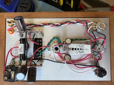
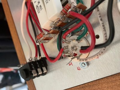
The initial build of my Crack got as far as the voltage test. The voltages were all within range except 1 and 7. The values were: 1) 155.4, 2) 170.3, 3) ~0, 4) 170.3, 5) 78.3, 6) ~0, 7) 155.1, 8) ~0, 9) 103.3, and 10) ~0. I'm not sure where the error is here, but I suspect 155.1 v for 7) is way too high. I'm thinking 155 for 1) is also too high. Any suggestions?

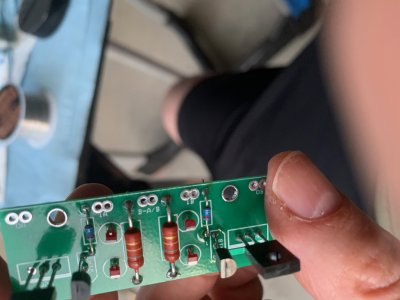
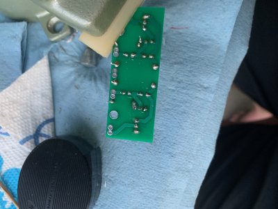
Also, I decided to resolder the LEDs since I couldn't tell if they were lit or not. (I build in the garage using daylight since that's all I've got.) I broke one of the leads for one of them during the reinstall. Is this the correct part for a reorder: Mouser 630-HLMP-6000 ?
Many thanks,

/d
 

Attachments

  • IMG_0453.jpg
    IMG_0453.jpg
    912.7 KB · Views: 11
On lower terminals, I would bend the wires up against the face of the terminal strip so they will stay put.  I would definitely do this on 2L.

The remaining HLMP-6000 needs its leads trimmed. 

You can run a wire jumper from A3 to A8, then recheck the amp to see if the voltages at terminals 1 and 5 both settle to where they should be.
 
Thanks, Paul.

I will add the jumper after bending the all of the lower terminal strip leads up. As a quick note, in the current picture the LED and the wire from the volume pot to the center pin aren't soldered. I had unsoldered them to try and start fresh with the LED solder joints. I'll reply shortly. Thanks again.

/d
 
Paul,

Not gonna happen today. When trying to wire the jumper I broke the other LED.

Unless.....

Any chance I can wire in resistors place of the LEDs to get the amp working until I get replacement LEDs? What would be the appropriate values in this case?

Thanks,

/d
 
The closest I have on hand is 562 ohm 1/2 w (Dale CMF55). Since I don't know the intent of the part (I'm assuming to draw down the current) I'm not sure if this value makes sense math-wise. If this won't work I'll just wait for the LEDs.

Thanks for all of you help.

/d
 
I mean, it's kinda wrong, but not so far off that it won't work.  Terminals 1 and 5 will show higher voltages that we would like, as will terminals 7 and 9.  I doubt they will be all that far off. 
 
Paul,

I got the resistors in as we discussed and the voltages were as follows: 1) 88.0; 2) 174.7; 3) 0; 4) 174.0; 5) 88.4; 6) 0; 7) 111.6; 8) 0; 9) 111.0; 10) 0. This suggests to me that I had previously incorrectly soldered my LEDs. Is this guess correct? After your last post I was expecting the values to still be pretty far off, but maybe the success of this test with the resistors temporarily in place of the LEDs indicates the robustness of the design.

Am I safe to replace the temp 562R resistors with the LEDs when they arrive from Mouser? Am I safe to test the unit with headphones now, or should I wait until I successfully have the LEDs in place?

Thanks for all of your help,

/d
 
Yeah, you can go ahead and use it.  You should see terminals 1, 5, 7, and 9 drop a little bit with the LEDs installed.
 
Thanks again, Paul.

About how long after I successfully have the LEDs installed do you recommend before I install the Speedball? Week? Month?

/d
 
Paul,

One more question (for now?!) with a long lead-in: The amp appears to be working perfectly. A few minutes after listening to the amp I first noticed the smell of the electronics heating up. When I touched the top plate it was warmer than I expected so I pulled out my IR thermometer. The temperature of the top plate after about 10 minutes of use was 42c. The 6080 tube is glowing quite bright and is very hot (which might be typical for this application) while the 12au7 wasn't near as bright or hot (relative to its size - again, maybe typical of this application). I didn't think the tubes were going to bring the top plate up to 42c alone. I measured the temp of some of the parts and was surprised at the temperature of the 3k 10w resistor - 67c. That's #@$% hot and is likely what is heating the top plate. So now the question: Is this typical of the design? I believe these big resistors are coming out when I put the Speedball in, but I want to make sure things are running correctly before moving forward.

Thanks,

/d
 
The 3K/10W resistors are rated to run all the way up to 155C.  We find at this temperature, lifetime is really short.  Even at 100C, lifetime is impacted, so we aim to stay under 100C.

The temperature of these parts is governed by the voltages in the circuit, so a 10K/3W resistor getting too hot would also have a bad voltage accompanying it. 

It is 100% normal for the top plate and the tubes in the amp to be quite hot.  The 12AU7 does not generate as much heat as a 6080 because it is a smaller device with a lower dissipation rating.  The funny thing is the 6080 could be run with 5x the plate dissipation and still be OK, now that would be hot!
 
Ran into another problem, this time with the Speedball. I wanted to get started on the Speedball upgrade while waiting for the LEDs to arrive from Mouser so I thought I'd stuff the boards. While checking my work I noticed that the pad between R1a and Q1a on the small circuit board seems to have a permanent solder bridge caused by the trace being at the surface of the underside of the board (please see attached photo). I believe the the trace is at the surface since the solder bridge (and resultant solder left-overs) have the exact same shape as the trace on the bottom of the board. No matter how many time I use a solder sucker or a solder tape I can't remove the bridge. Looking at the plans on pg 7 of of the Speedball installation manual R1 (237R) should connect to Q1 (PN2907a) (this is somewhat confusing on the plans since there are two parts labeled Q1- PN2907A and 2N2222A -, Q2 - MJE350 and TIP50C -, R1 - 31R6 and 237R -, and R2 - 150K2W and 47K2W - maybe a possible spot for a revision??. Actually there are two D1 and D2, too, but they are all the same part!) on the emitter (pin 1, far left looking at the flat edge of the part). Looking at the board the bridge between the resistor and the transistor appears also to be at the emitter (pin 1) (see photo). If I understand this correctly then the solder bridge caused by the trace at the surface shouldn't be a big deal when I install the small circuit board since the solder bridge is essentially a redundant trace. If I have it wrong I may need a new board. Please advise. Thanks, /d
 

Attachments

  • IMG_0463.jpg
    IMG_0463.jpg
    431.7 KB · Views: 15
  • IMG_0466.jpg
    IMG_0466.jpg
    521.8 KB · Views: 11
They are supposed to be connected.  You probably have burned off the solder mask that would otherwise be covering that trace.  Just leave it alone, eventually if you keep heating it the trace will peel off and you will need a new board.

We have a Q1A, Q2A, etc. on each board.  There's no need to continue the indexing when moving on to the next board, especially considering many of our boards go in multiple different kits.
 
Back
Top