Im still a moron - problem at Shunt regulator voltage test

gregoryahunter

New member
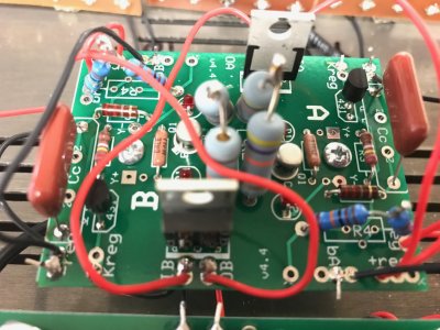
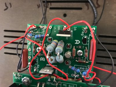
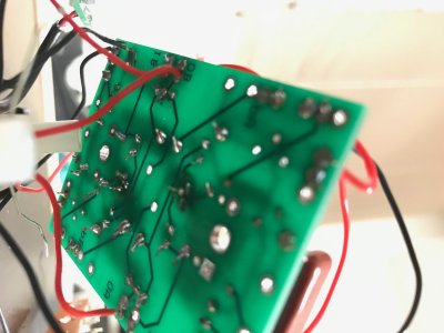
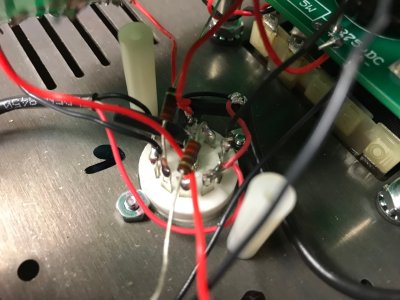
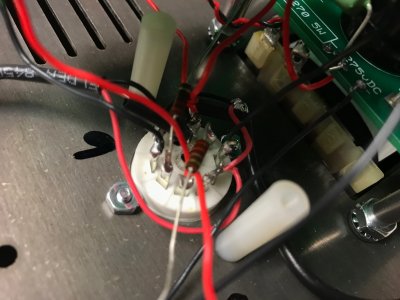
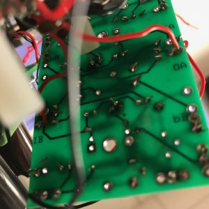
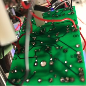
I have been good up to the Shunt regulator voltage test, but Im failing here.  The D1wire test fails.  I get a few tenths of a mV with black lead clipped to T23 and the red clipped to the red wire off of D1.  The tube glows.  Only the 2 LEDs on the "A" side of the board glow.  When I do the same test but with D6, I get the expected voltage up to about 330, that then drops to 222V.  The tube glows.  But still only getting the "A" side LEDs to light up.  I have tried to go over all of the solder joints (but to be honest, I dont know how to get inside to the deepest parts on the board.

Does this set of findings point to a specific solder joint that I can try to touch up, or is it a case of "go back over everything"?

Thanks


I'd post photos if possible.  You can heat up the joints for the little resistors that go down to the socket so you can flip the board up and take photos of both the 9 pin socket and the bottom of the PC board.

There is a jumper from IA to IB that should supply the unregulated B+ to each half of the PC board, is yours present?
 
Ok - I took a bunch of pics - sorry if I over did it. 


Addendum - can anyone else see the pictures I uploaded?  I can see them on my computer, but when I look at the thread on a comuter at work - the uploaded pics dont show up.
 

Attachments

  • 1.jpg
    1.jpg
    626.3 KB · Views: 17
  • 2.jpg
    2.jpg
    612.7 KB · Views: 6
  • 3.jpg
    3.jpg
    589.6 KB · Views: 5
  • 4.jpg
    4.jpg
    718.5 KB · Views: 1
  • 5.jpg
    5.jpg
    691.8 KB · Views: 2
  • 6.jpg
    6.jpg
    533.8 KB · Views: 7
  • 7.jpg
    7.jpg
    548.7 KB · Views: 0
  • 8.jpg
    8.jpg
    769.2 KB · Views: 6
  • 9.jpg
    9.jpg
    465.9 KB · Views: 6
  • 10.jpg
    10.jpg
    479.2 KB · Views: 1
  • 11.jpg
    11.jpg
    509.1 KB · Views: 1
  • 12.jpg
    12.jpg
    597 KB · Views: 2
  • 13.jpg
    13.jpg
    579 KB · Views: 1
  • 14.jpg
    14.jpg
    583.6 KB · Views: 1
  • 15.jpg
    15.jpg
    666.7 KB · Views: 0
  • 16.jpg
    16.jpg
    546.2 KB · Views: 1
  • 17.jpg
    17.jpg
    581.6 KB · Views: 1
  • 18.jpg
    18.jpg
    535.8 KB · Views: 4
  • 19.jpg
    19.jpg
    393 KB · Views: 1
  • 20.jpg
    20.jpg
    389.7 KB · Views: 3
There are a couple of places you can get in trouble with this:

1.  The MPS4250 being swapped with a TL431 can cause some problems, but not likely the ones you have.
2.  The 1085 regulator being swapped with an MJE5731A.
3.  Backwards LEDs on the board itself. 

 
Back
Top