Help to troubleshoot my Crack (RESOLVED :)

ju29

New member
Hello,

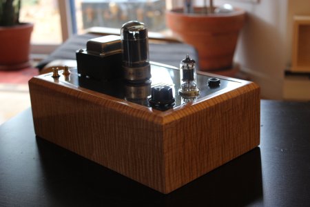
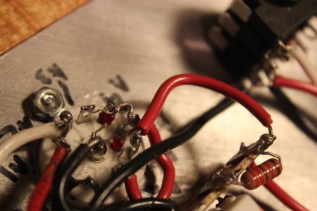
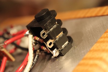
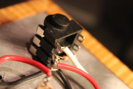
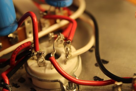
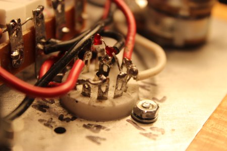
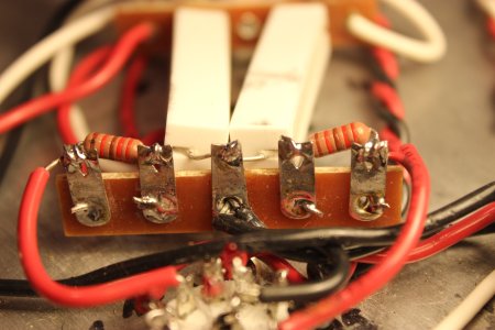
I built my Crack yesterday (speedball not installed yet). Everything went as it supposed to until the voltage checking (terminal 13 more precisely). My hand shaked and I did a short-circuit touching the 270 ohm 5w resistor (the one between the terminal 21U and the 15U) and the terminal 13 during the checking. There was a sharp little "bang" like a cracker.

The tubes seems to be ok, they still glow..// (?), the fuse is also ok.

As the result I tried the Crack with cheap headphones in cas it could damage my 650. It worked fine until the left hear stopped working in the headphone after a couple of minutes. Then I switched off the Crack for few minutes and turned it on again. It worked ok and then again, the left hear stop after about three minutes.


The voltage changed between before the short-circuit and after (terminals 1 to 12). The ones at zero remained at zero.


HERE ARE MY VOLTAGE MEASURES BEFORE the short circuit () and AFTER :
(The resistance check was spot on. I haven't checked them again since the short-circuit)

Terminal 1 : (before : 83) // after : 89 (should be 75-90)
Terminal 2 and 4 : (173) // 198 (should be 170)
Terminal 5 : (80) // 88 (I have to double check, I wrote it changed to 88 to 0 then 88 and so on) (should be 75-90)
Terminal 7 : (109) // 121 (should be 100)
Terminal 9 : (109) // 0 (!!!) (should be 100)
Terminal 13 : (?) // 198 (should be 170)
Terminal 15 : (?) // 210 (should be 185)
Terminal 21 : (?) // 223 (should be 206)

Terminals A1 and A6 : (?) // 89 (should be 90)

Terminals B1 : (?) 89 (should be 90)
Terminal B2 : (?) // 198 (should be 170)
Terminal B3 : (?) // 121 (should be 100)
Terminal B5 : (?) // 198 (should be 170)
Terminal B6 : (?) // 0 (!!!) (Should be 100)

Terminals 3, 6, 8, 10, 11, 12, 14, 20, A2, A4, A5, A7, A9, B7, B8 : (0) // 0


Clearly there's a problem with the measures of the terminals B6 and 9. They are at 0 instead of 100 (again, the measure of the terminal 9 was ok with 109 before the short-circuit...).


Would someone have an idea of what should I check and should I do to troubleshoot my Crack now ??


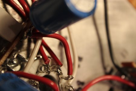
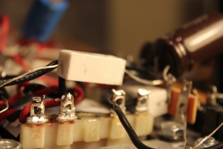
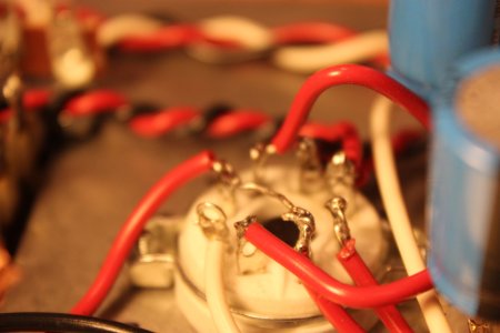
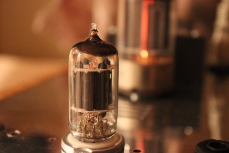
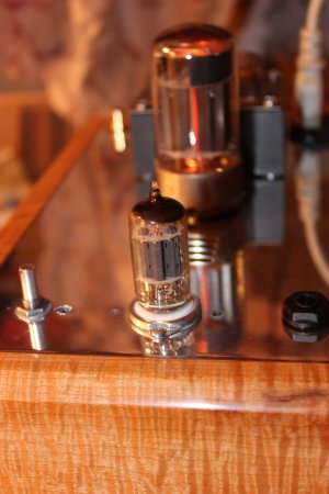
My guess is that one of the capacitors is dead or damaged. But that's only my guess (I don't know anything in electronics...). Also the "little" tube has to top black on the inside (seems like black powder). Is that normal ? I didn't pay attention before and don't remember if it looks normal like that...  (cf. picture below) It still glow but much less than the "bigger" tube.


THANKS A LOT FOR YOUR HELP ! I was SO close to complete the build without any problem, arghhh.... :)
 

Attachments

  • 01.JPG
    01.JPG
    1.3 MB · Views: 97
Where you had your accident would have no impact on terminals 6-10.

You most likely have a bad solder joint, backwards 100uF capacitor, or wiring error around the octal socket.

-PB
 
Thanks for your reply PB !

Ok, I'm going to check again. What I don't understand is that the terminal 9 had the right measure before the short-circuit (I checked several time for each terminal until the 13th and the short circuit...). And then, after the short-circuit, the measure was 0. I guessed it had a link between both. There other incorrect measure (that is at 0 instead of 100) is B6.


So you can confirm me, a short circuit like that cannot damage parts (capacitors or resistors) ? I'm quite sure the short circuit occurred when I touched the 270 ohm 5w resistor and the terminal 15. But I may have seen it wrong and could have been with the terminal 14. Would your analyze would be the same in that case ?

Thanks again,

Julien
 
ju29 said:
So you can confirm me, a short circuit like that cannot damage parts (capacitors or resistors) ? I'm quite sure the short circuit occurred when I touched the 270 ohm 5w resistor and the terminal 15. But I may have seen it wrong and could have been with the terminal 14. Would your analyze would be the same in that case ?
Terminals 14 and 15 are in the high voltage power supply, terminal 9 and B6 are fairly well isolated from the power supply, so you need to look at the 3K resistor 100uF cap, and associated connections to determine why you have 0V at 9 and B6.  (This would've likely presented itself as an issue without the incident at T14/15)
 
Ok, quick update.

- I checked again all soldering I wasn't sure and desoldered them.
- checked all the wiring.
- desoldered/resoldered all wires, capacitors and transistor close to Terminal 9 and B6.
- checked the resistance again (all ok).
- checked the voltage and all the measures were almost perfect  even for terminal 9 (103) and B6 (102) but for few minutes only... Then Terminal 9 and B6 were at 0 and some others values slightly changed (increased).  :'(


As I wrote in my former message, when I tried the headphone, the sound worked perfectly for 2 or 3 minutes and then the sound of the left hear stopped.


I guessed there were a correlation between both so I wanted to try the headphone and checking settings in the same time (safely). I had no other choice to check this (cheap headphones that works perfectly with others devices).


So, after 5 minutes I plugged the Crack again. The sound was perfect and all the voltages measures were almost perfect (even Terminal 9 and B6 at 102 and 103). Then when the sound of the left hear stopped after 2 minutes the measures changed again (terminal 9 and B6 at 0 + other measures that slightly increased).


So.....  since the measures are fine for the 2 first minutes I guess my wiring + my solders are both ok..
It remains the hardware (bad components). Am I right ???

What do you think about it ?

If the hardware is the issue, any advices of where I could buy the same components (resistors//capacitors) ?


Thanks for you answers and you help. It will be fixed ! :)
 
If you had a failed component, it would never work. An intermittent problem is a solder problem. You have a joint that ceases to make contact as it expands with the heat of running the amplifier. Fix your solder and fix your amp.
 
Thank Joshua Paul for your replies. Ok, I understand. I'll check again and will redo the solders.
I hope I'll find the issue soon ! :) 
 
I desoldered in the meantime about 90% of what I built. During this I broke a leg (may be not the right term) of one of the HLMP 600 red led...  :-\ I'll have to order some spares.

 
Hello, after reading the instructions of the speedball upgrade (that I got in the same time of the Crack and that I plan to install.. one day :) I realized there were few leds in the package. So I took one and used it so as to rebuild my Crack (I ordered new leds from BH and there are on their way...)


So... I resoldered what I had undone (85/90%) and then check the measurements again.
Resistance check was ok but the exact same pb occurred this the voltage check :
every measurements are fine and after 2 minutes B6 and terminal 9 are at 0 (and the others measures that were fine increased slightly...

Following the instructions of Paul, here are a couple of pictures. I didn't take all solders in pictures but that's a start. Would you mind to have a look at it and tell me what you think ?

Now that I understand the pb is caused by bad solder where could possibly be the location of all the bad solders that could lead for sure to this issue ? I mean, can the pb come from any solders or is it no use to check some because they cannot have any effect on the issue ? (I hope I'm clear, english is not my first language so I try my best.. :) )

Thanks a lot,

Julien
 

Attachments

  • 14.JPG
    14.JPG
    1.3 MB · Views: 55
  • 13.JPG
    13.JPG
    1.2 MB · Views: 61
  • 12.JPG
    12.JPG
    1.3 MB · Views: 60
  • 11.JPG
    11.JPG
    602.6 KB · Views: 55
  • 10.JPG
    10.JPG
    621.4 KB · Views: 61
  • 09.JPG
    09.JPG
    1.4 MB · Views: 74
  • 08.JPG
    08.JPG
    533.4 KB · Views: 67
  • 07.JPG
    07.JPG
    1.5 MB · Views: 59
  • 06.JPG
    06.JPG
    579.9 KB · Views: 72
  • 05.JPG
    05.JPG
    1.6 MB · Views: 62
  • 04.JPG
    04.JPG
    1.4 MB · Views: 77
  • 03.JPG
    03.JPG
    1.3 MB · Views: 73
  • 02.JPG
    02.JPG
    1.2 MB · Views: 82
  • 01.JPG
    01.JPG
    1.4 MB · Views: 80
The black wires at 3 could do with some solder both sides of the tag strip but I don't think that is your problem area.
 
Ok, I desoldered at least twice each of them. Others solders, closed/linked to B6 and T9, more than that...
...and the same pb occurs.


Now, honestly I'm completely lost and really don't know what to do next. I feel sad and frustrated to have spent so many hours (days) for nothing. I just don't get it. I know it's an easy kit and there's no billion of places to check. With the $$ conversion, repair service is about 170$ + shipping (CAD) so it's not quite really an option for me right now.


I know I repeat myself with this question but does it have to be a bad soldering, for sure ?
Are there specifics checking I could do to try to locate the issue very precisely ? 

(Thanks Deluk for your reply at my last message. I checked also this one but didn't solve the pb)
 
Both sides of the tubes light up?
It happens after something grts hot enough, 2 mins. And all solder joints are rewetted/ reheated.
Is it unthinkable that there is a problem with the 6080 tube?
Maybe it should be swapped for another one?
 
Yes, the 6080 lights on both sides and much more than the other small one. I've just checked, both still glow when the music stop in my left hear.

I attach 2 pics of them.
 

Attachments

  • 02.JPG
    02.JPG
    625.1 KB · Views: 74
  • 01.JPG
    01.JPG
    1.3 MB · Views: 97
Might be grasping at straws here. Have You take the 6080 out and cleaned the pins and checked that the socket is tight for all pins?
 
Hi, I checked and the socket tight for all pins and for both tubes.

I didn't mention because I hadn't really paid attention but when I switch on the crack only one hear (the right one) works for about 10 to 15 seconds. Then there's a pop in the left hear and the crack works fine for 3 to 6 minutes. And after that no sound on the left hear anymore.

Resoldered again a few this morning but same pb. Can the issue be related to the headphone jack or there's absolutely no link between this part and my pb ?


Isn't it also possible it could be a nicked/broken wire rather than a soldering problem? Might be time to try a careful chopstick test to see if wire movement causes any static/pops/noise.
 
Thanks for your reply Dale. I asked myself this when I almost desoldered everything the first time. I would remplace a couple of wires just be 100% sure but I don't have that much left. Do you know if there's a way to check their integrity them without removing/desoldering them ?

I also wonder if one of the tube sockets could be the pb (just a suggestion... I don't know if that's possible // ??)


....Is HAS to be somewhere..


I will resolder few others later, again... For now I do have to go on my guitar build. Much easier  :-\
 
Again, This looks like intermittent contact. Perhaps a solder joint that you are missing each time you go around them or perhaps a broken wire as suggested by others. Taking apart your build and putting it back together is also an occasion to break parts. Some joints with multiple wires or parts require more heat and solder to be adequate. You do not necessarily have to undo the connexions to make them sound, only reheat them and apply a bit more solder. Make sure you have good mechanical connexion (good loop around the terminal) before soldering.

I would suggest that you ask a friend to look at your build and check it against the manual. A fresh pair of eyes could see something that you keep missing.

As PB said, measure the 3K resistor between 3U and 9L to make sure it is good and inspect around there to see that everything is okay.

I am not an electrician, but some of your voltages that are on the high limit side might be related to your mains voltage. I had similar readings in some of my kits, and found out that the voltage coming into my house was around 125 volts. The manual says that the voltages were made with an AC mains voltage of 119VAC.

Where in Canada are you located? I am in Montreal. I could look at your amp if you are nearby. I have spare tubes and parts for the Crack.

Richard
 
Back
Top