first time build, everything went pretty clean but... [resolved]

xaanix

New member
resistances checked out, no issues, all behaved exactly as described in the manual.

when i got to voltage checks, i see most voltages are correct, however some voltage are much higher than expected.  Here is my full list of voltage checks.

B1 78.3
B2 169
B3 101
B4 152 (manual lists 90)
B5 169.2
B6 152 (manual lists 100)
B7 0
B8 0
T1 78.3
T2 169.5
T3 0
T4 169.5
T5 153 (manual lists 75-90)
T6 0
T7 101
T8 0
T9 153 (manual lists 100)
T10 0
A1 153 (manual lists 90)
A2 0
A3 0
A4 0
A5 0
A6 78
A7 0
A9 0

12T 0
11 0
12 0
13 170
14 0
15 193
20 0
21 217

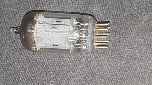
Seems like a chain of 'hot voltage' is running through the build but does it originate from the tube?  (both b4 and b6 are hotter than expected and would be ouptut directly from the power tube no?)

The led's seem to behave properly, the tubes do heat up and glow in what appears to be a normal way (but i'm a newb so what do i know).  Could this be tube variance?
Am i ok to plug in headphones?

I have 2 other questions related to this voltage testing:

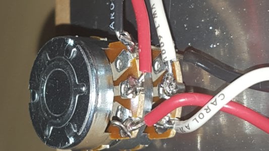
It asks us to turn the volume all the way down.  Well, which direction is down?  (would like confirmation of this since it is not specified anywhere).
 
Hi,
There are other voltages that are not correct apart from the ones in red. The guys from BH will help you out.
Don't use an amp that does not pass all the checks.

Turn the volume control to the left (anti-clockwise) all the way, that is minimum (if wired correctly) ;).
 
The big issue here is A1, which is creating the rest of your problems.

I will assume that this is a stock Crack with no Speedball, if that isn't the case, let me know.

A1 will be higher than it's supposed to be when half of the 12AU7 is not conducting properly.  This can happen from:

1.  Half the 12AU7 isn't being heated (do both halves of the 12AU7 glow?).  This problem happens when the solder joint at A4 and A5 isn't well flowed.
2.  The 22K resistor between T1 and T2 isn't well soldered.
3.  The LED at A3 is broken or not soldered properly.  You can jumper A3 to A8 if you find signs that this is the case, but I recommend working on the other options first.
4.  The wire connecting to A2 has a poor ground reference, which can be a bad solder joint on this wire, a missing ground jumper between the lugs on the volume pot with the black wires, etc.  (You can measure the DC voltage carefully at A2 and A3 and post those for more detailed information)

-PB
 
Thank you so much -- this feedback is tremendously helpful and very appreciated. 

Yes i am using the stock crack.  I will attempt to resolder A3 which i suspect could be a problem based on something i observed while building and re-test A4 and A5 (although i dont expect an issue there).  The manual doesn't mention, but i assume i would want to remove the tube in socket A for this?  That tube was not easy to get in (i feared i was going to break it like an egg).

Regarding A3 -- I did notice that the led on A3 powering up initially ( and reproducably) when I plugged in the cord, but it would go dark after a bit.  I also believe i noticed one of the resistance checks fluctuate (I think in A3) as i was taking the measurement, probably a useful clue.  Another concern is that while heating the center peg, i may have touched the LED at for a moment or two.  Maybe i cooked the LED... (not sure why it would still light up initially though).

So you're saying on your bullet #3 below that i could just direct wire A3 to A8 -- and that produces a workable circuit?  The manual mentions these LED"s set the bias voltage, however i'm not really familiar with that concept.
 
resoldered a few joints.  I did see a problem with  T18.

Unfortunately i'm still seeing this issue.

I tried measuring across T1 and T2 to see about the resistor there and see it measuring a bit above 22k ohms. I also find the outside RCA (white) jack center pin measuring at 106k ohms.  The red measures 98k ohms.

I have the following behavior:

upon energizing the circuit, both LEDS are initially off, then begin to glow faintly and then more strongly at the same time.  After about 6 seconds (upon further testing, this varies, sometimes the circuit stays working normally for a few minute) -- (and after reaching what appears to be full brightness, the A3 LED suddenly begins to flash for approximately 4-5 seconds, then eventually it goes dark and does not return.  After powering down I can power back up and this behavior repeats itself.


I didn't measure exhaustively the voltages but T5 is still showing 150 volts.  I'd like to get a reading of T5 while it powers up..  Will give that a shot and see if it is just suddenly shutting down..
 
Resoldered joints on T1-T2, and the Center Pin for socket A.

It's definitely a busted connection somewhere.  If i tap on the T1-T5 bridge I can make the A3  LED flicker,  (the other LED stays solid) sometimes if the problem manifests tapping the baseplate or tapping the T1-T5 bridge, or tapping the T1-A5 wire will  it will return the entire circuit back to normal for a while. Tapping the T1-A5 connecting wire seems to have a stronger effect.  Wondering if the reason i had such trouble getting the tube in is that the pins for the socket werent aligned.  Thinking the connection into the tube from A5 might be flaky... it seems slanted.  Going to try to take the tube out tomorrow and see if i can look down into the sockets from above and figure out whats going on..


I tested connection to A2, (resoldered this, and the other side)..  Looks good, tests good..  didn't seem to have an impact.
 
In my tube noob days I sometimes added too much solder to the socket pins and it would leach down to where the tube pins go and cause a bad connection. 
 
Here are some pics of my solder points.

I'm still thinking the problem is with the socket or the tube, or possibly the LED at this point. (not sure why it would blink and then go out though).
 

Attachments

  • 20160413_221412.jpg
    20160413_221412.jpg
    1.4 MB · Views: 151
  • 20160413_221447.jpg
    20160413_221447.jpg
    1.5 MB · Views: 142
  • 20160413_221200_001.jpg
    20160413_221200_001.jpg
    1.9 MB · Views: 148
While you have amp upside down - Carefully plug in the tubes and power cord and carefully power it up. Then take a plastic pen or other non-conductive tool and poke around the connections to the tube socket to see if you can reproduce the on-off behavior.
 
Sure Doc!

In case you're interested in seeing it -- here is movie i took last night of what was happening:
https://drive.google.com/open?id=0B9VdJs7a5ON_YjZIYXRYWVZ0Z1E

It doesn't show the response to banging/tapping, as i figured that out later.  I will do as you suggest however and report back my findings.

I'm willing to order a new socket/tube/and LED's to help test/isolate and then fix the issue.
 
If jostling the amp makes the behavior come and go, then you have a loose connection.  The one that I see that looks the most flaky is the solder joint on the lower level of terminal 2.

-PB
 
Terminal 2L?  I thought that was one of the better looking ones.  :-\ What looks wrong with it?

Here's some pics of some of the other components.
 

Attachments

  • 20160415_061049.jpg
    20160415_061049.jpg
    3.5 MB · Views: 48
  • 20160415_060946.jpg
    20160415_060946.jpg
    3.3 MB · Views: 46
  • 20160415_061300.jpg
    20160415_061300.jpg
    2.4 MB · Views: 117
  • 20160415_061821.jpg
    20160415_061821.jpg
    2.3 MB · Views: 147
  • 20160415_061912.jpg
    20160415_061912.jpg
    2.1 MB · Views: 62
Sorry to say that many joints there look to be "glued" on rather than having nicely flowed solder. Maybe this is old solder that has poor flux now. Can also be caused by a bad or dirty solder bit that's not properly tinned.
 
You're right, this was certainly old solder (not even sure how old) and was done with an old iron which was not in the best shape.  I just ordered a weller soldering station for 90$ on amazon, as well as some solder wicks.  They should be here today and tomorrow.  Based on your post I'll order some solder too since it seems that's needed. 
 
status update:

I attempted to prod nearly all of the terminals with a plastic pen and could find no real correlations between which terminals I poked and the effect on the A3 LED. (all of them, even on socket B, seemed to affect it equally)

I did put my phone under the amp and tapped very lightly on the tip of the 12AU7.  This seemed like a strong correlation because of how softly i was touching it and the fact that it did reliably cause the A3 LED to go on and off.  I'm thinking either a problem with the 12AU7 or something with the socket.

I did monitor the voltage of the headphone jack during the problematic behavior.  After 'boot up' of the amp, the voltage did increase but stayed below 9 volts (think it peaked around 6, and then declined).  Since normally the startup of the amp never experienced the bad behavior (it seemed only possible once the tubes heated up) I never got to see any abnormal fluctuations during the startup period.  Voltages went down to 0 on the jack after about 4-5 seconds after the peak.  Then after a while i began to tap the amp and got the the A3 LED to flash, Once this happened I saw wildly fluctuating voltages on the headphone jack (tip), 24v was certainly hit several times while the problem was occurring.  Maybe this provides a clue?


Since the volume control was brought up as possible cause, and because i was not terribly happy with the tightness of my braid (after seeing doc's photos of one of his builds), and because I now have a well tinned iron and some fresh solder, I decided to re-braid and re-do all the connections on the volume control.  During this process i must have damaged the volume control as I am no longer able to measure any resistance across the 2 red terminals.  I can still measure resistance across the 2 white terminals (which is up around 106 ohms, as it was before).  So, sadly, I'm going to need a replacement for this part.

I had resoldered T1L, T2L, T3L, A-Center, and A1, and A2, and I had soldered the input termals (all 3 wires, and all of the connections to the volume control (after i broke it apparently). 

To proceed, and so multiple parts orders aren't needed (I'd like to minimize shipping delays) I'd like to order the following parts:
1 12AU7
1 socket A
1 socket B
4 LED's
1 volume control
24" more of each color of wire (black/red/white)

I don't mind paying for this stuff, my priority is to get this completed as soon as I can.


This shows the behavior of tapping on tip the 12AU7 https://www.dropbox.com/s/8mz7mrq5ik377v6/20160416_191357.mp4?dl=0
 
First time builder and this is my foray into tubes, so unfortunately I have no spare parts to test with.  My intuition tells me it's the tube but since I'm noob at this was looking for others opinions.
 
Its either a bad tube or a bad solder joint somewhere. If you have a music store nearby you might be able to pick up spare tube there. The 12AU7 is a common tube used in guitar amplifiers. The place down the street from me sells 12AU7 JJ's for less than $15. FWIW I had a 6SN7 do the same thing. One of the internal wires (inside the glass envelope) wasn't terminated at the pin properly causing an intermittent connection. I replaced the tube and all was fine.

You may want to post your location. There may be a fellow bottlehead nearby that can help. We are a pretty friendly group. Alternatively you could give me your shipping address in a private message. I could send you a known good tube or two. I have more than I'll ever use in my lifetime.
 
Back
Top