Final Voltage Check

bradtsakeris

New member
Hello,

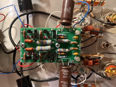
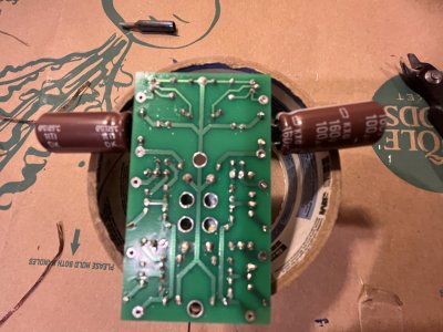
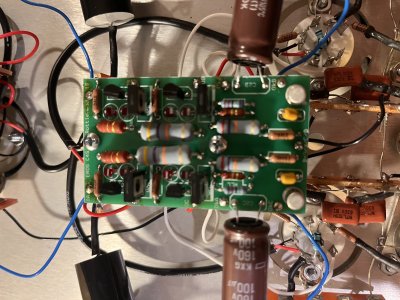
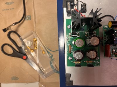
I have completed all the steps of the EROS 2 and am doing the final voltage check. I am not getting the correct voltage on OC, OD, OkA, OkB, OkC, or OkD. I have uploaded a picture of the board to see if there is anything you notice I did wrong.

Thanks,

Brad
 

Attachments

  • Eros 2.JPG
    Eros 2.JPG
    2 MB · Views: 37
For every solder joint on that board that doesn't have an LED, you need to use a lot more heat to get the solder to flow into the through hole on the board.  It also helps greatly to actually post the voltages you're seeing at each terminal.
 
Hi Paul,

I am getting the following voltages from each terminal
IA = 217.8
IB = 220.3
OA = 215.2
OB = 140.1
OC = 100.2
OD = 102.5
OkA = 6.86
OkB = .4
OkC = 25.7
OkD = 4.7

What temperature should i set my solder to? I have been using around 650 degrees but my solder can go up to 850 degrees.
 
Hi Paul,

I have re-soldered every joint on the C4S board and am still getting the same voltage readings as listed below. Any thoughts where I should go next?
 
Hi Paul,

I removed all of the wires to be able to remove the C4S board and flip it upside down so I could re-solder all of the holes. I have attached a picture for you to see. I then re-soldered the wires in the correct holes and ran the voltage check Here is what I'm getting now.

IA = 287.7
IB = 288.1
OA = 286.9
OB = 286.6
OC = 208.2
OD = 208.1
OkA = .5
OkB = .4
OkC = 3.51
OkD = 20.0

Any thoughts on what to do now?
 

Attachments

  • Eros c4s 2.JPG
    Eros c4s 2.JPG
    1.8 MB · Views: 19
  • Eros c4s 1.JPG
    Eros c4s 1.JPG
    2 MB · Views: 10
Double check that all of your tubes are glowing. The EF86 tubes will be hard to see the glow from. A very dark room is helpful.
 
Hi Dan,

None of the tubes are lighting up. Not sure why that is. I was at least getting the 12AX7 to light up before. I just removed the fuse and checked the volts and I'm getting 0. It looks like it may have blown.
 
Hey Brad, after our conversation today I picked PBs brains a bit about what you were measuring on the heater supply. He suggested that maybe either the 124 ohm Rset1 resistor or the 499 ohm Rset2 resistor has the wrong value installed, or perhaps they are correct but need a bit of a solder reflow. Makes sense and I should have thought to mention that. So you might have a look at those. They are just inboard of the LM1085 chip.
 
Hi Dan,

I re-soldered all 3 boards to make sure they all have solid solder on every joint. I installed all of the tubes and they are still not lighting up. I checked the voltages and am getting the following readings:

IA = 301.9
IB = 301.9
OA = 299.5
OB = 299.6
OC = 210.5
OD = 206
OkA = .81
OkB = 6.9
OkC = 3.27
OkD = 20.1

These readings are all way higher than the last readings. I'm sure where to check from here. Let me know your thoughts.
 
If the tubes aren't glowing, the high voltage readings don't really matter nor do they mean anything.  You have to focus on getting 6.3V DC across the + and - pads on the low voltage output section of the power supply board.  Until that is correct, the tubes will not light up and the high voltage readings will be wacky.
 
Take the power supply PC board off and send photos of the top and bottom.  Also triple check that the 1085 regulator is installed instead of a 5731A transistor, as they both look similar.
 
Hi Paul,

Here is a picture of the top of the board. I'm hoping you notice something here before I go an un-solder all the wires to be able to show the underside. Let me know thoughts.

Best,
Brad
 

Attachments

  • EROS Power Board.JPG
    EROS Power Board.JPG
    2.1 MB · Views: 11
There's all sorts of wrong with this.  Can you slip just the shielded twisted pair connections out of the + and - pads where the 6.3V is supposed to be and recheck those outputs?
 
Paul,

Sorry, I'm a bit of a newbie with all this stuff. Do you want me to remove the shielded wire from the board at the 6.3v? What do I need to do after doing that?
 
Let's slow this down. Don't remove the wires yet. If you recall I explained during our phone call that you want to measure with black test lead to 6.3v - and red lead to 6.3v+. For this measurement you don't want the black lead connected to the ground post. Give us that reading from 6.3+ to 6.3- . And please let us know if you double checked the values of the 124 and 499 ohm resistors mentioned in my previous post.
 
Back
Top