Failed Final Voltage Check

figby

New member
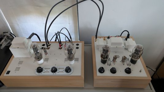
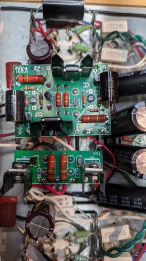
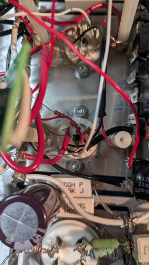
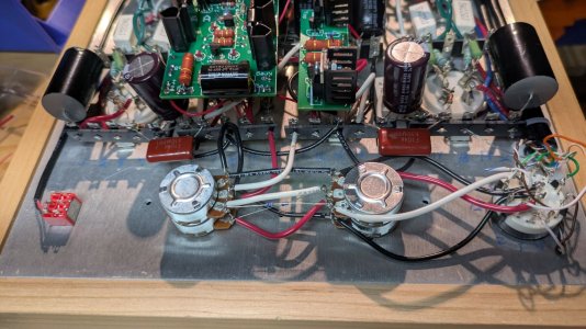
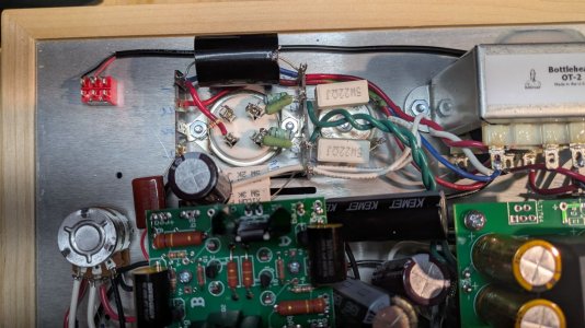
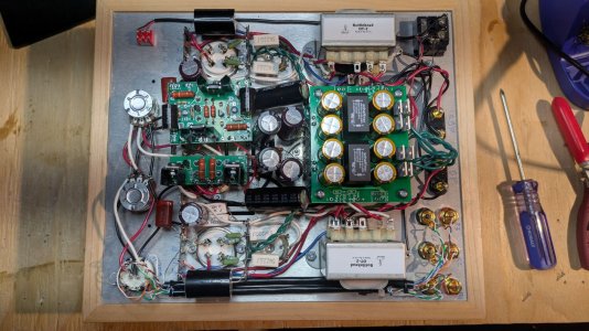
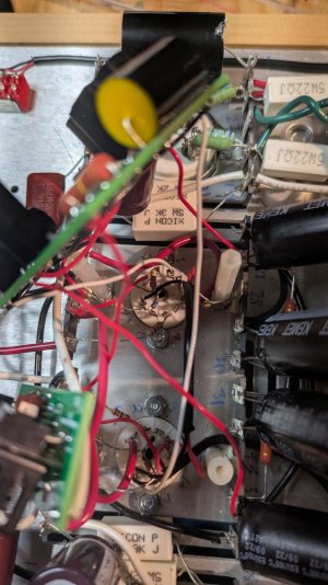
Passed the resistance check, but failed the voltage check. I've walked back through the build, checked solder joints, etc. but can't find the issue. Any thoughts on where to look?

1. 365 VDC (-20mv)
2. 395 VDC (0)
3. 0 VDC (0)
4. 0 VDC (0)
5. 0 VDC (0)
6. 58 VDC (40.2mv)
7. 170-230 VDC (-.9v)
8. 0 VDC (0)
10. 0 VDC (-363mv)
11. 0 VDC (0)
13. 0 VDC (0)
14. 170-230 VDC (206.8v)
15. 58 VDC (60v)
16. 0 VDC (0)
17. 0 VDC (10mv)
18. 0 VDC (0)
19. 395 VDC (395v)
20. 365 VDC (365v)
21. 58 VDC (38mv)
22. 58 VDC (38mv)
23. 0 VDC (0)
24. 58 VDC (38mv)
25. 58 VDC (38mv)
26. 0 VDC (0)
27. 390 VDC (0)
28. 0 VDC (0)
29. 0 VDC (0)
30. 398 VDC (409v)
31. 399 VDC (402v)
34. 392 VDC (394v)
35. 0 VDC (0)
36. 58 VDC (61v)
37. 58 VDC (61v)
38. 0 VDC (0)
39. 58 VDC (61v)
40. 58 VDC (61v)
 
Did you plug one of the 2A3s in with one or both of the fat pins in the wrong holes?  If so, you're going to need to check the 130 Ohm 2W resistors in the power supply to see which one(s) you cooked.  The socket contacts may also need to be bend back together a little bit to grab on the skinny pins again.
 
The resistor between 27L and 30L is indeed cooked...thank you!

I double checked and I hadn't plugged in either 2A3 incorrectly, so that's a bit worrying that the issue might be hidden somewhere else. In the meantime, I'll put in a request for some replacement 130 Ohm 2W resistors and continue to check the circuit for possible shorts or mistakes until they arrive.

 
A backwards cathode bypass cap around the 2A3 socket on that side would also cause similar issues. (the 220uF/250V by the socket)
 
Found it!

I didn't clip a drain wire close enough and the stub had worked its way up and was in contact with the red wire from 27U where it connected at IA on the bottom of the PCB. Absolutely no idea how it managed to get up there but I clipped the drain wire stub flush and repositioned the twisted pair wire. Replaced the resistor (again) and it passed the voltage test without a problem. Listening to it now - sounds amazing.

Thank you for the assist!
 
Well....I just couldn't leave good enough alone.

After enjoying it for a day, I installed the DC Filament Supply upgrade, passed voltage check and listened to it for another day. Sounded really nice.

Installed the Shunt Regulator upgrade and the voltage check was:

IA 249V
OA 306V
KregA 3.36
IB 348V
OB 303V
KregB 2.08

I get no sound from the right channel and the balance no longer works at all. Moving the pot all the way to the left or all the way to the right has no effect. Music only plays on the left channel at the same volume. I took the Shunt Regulator off, double checked all the components on the PCB and the wiring on the back and stepped through all the instructions...everything is as/where it should be. Same for the DC Filament Supply. Also did a thorough debris check, trying to not make the same mistake again.

Any ideas?

On the plus side, it looks really nice next to my BeePre2.
 

Attachments

  • PXL_20250523_215928100.jpg
    PXL_20250523_215928100.jpg
    190 KB · Views: 10
IA can't be less than OA on the SR board, that doesn't make a ton of sense.  Can you post some build photos so we can have a look? It's probably also worth just double checking that it's 249V on IA rather than 349V.
 
Yes, couldn't read my own handwriting, IA is 345V.

I've attached several photos of my build, many thanks for the help.
 

Attachments

  • PXL_20250526_192756980.jpg
    PXL_20250526_192756980.jpg
    245.5 KB · Views: 9
  • PXL_20250526_193025556.jpg
    PXL_20250526_193025556.jpg
    243 KB · Views: 8
  • PXL_20250526_192820158.jpg
    PXL_20250526_192820158.jpg
    247.7 KB · Views: 10
  • PXL_20250526_192748956.jpg
    PXL_20250526_192748956.jpg
    244.9 KB · Views: 9
  • PXL_20250526_192741921.jpg
    PXL_20250526_192741921.jpg
    248.7 KB · Views: 4
  • PXL_20250526_192522010.jpg
    PXL_20250526_192522010.jpg
    237.5 KB · Views: 8
  • PXL_20250526_193017319.jpg
    PXL_20250526_193017319.jpg
    240.5 KB · Views: 8
The ground wires on the left channel portion of the balance pot don't look to be soldered.

Your SR upgrade is probably working fine, but I bet the left channel half of the original C4S is giving you an improper reading (OA or OB on the narrow C4S board is probably way off, which would happen from a faulty ground reference).
 
Back
Top