Dhouse7516
New member
Hi Paul and Doc, I'm in a predicament and hope you might have some advice.
After building and installing the shunt board, I did the voltage check and passed (I don't recall the actual measurements, it's been a while). I then proceeded through the rest of the build, passed final the resistance test, but failed the final voltage check on the C4S board. The B side of the board was fine, but all the values on the A side were off (If I recall correctly, they were low - apologies, but I did not write the actual values down at the time). I double-checked all the solder joints and connections on the C4S and A,B, and C sockets and they looked solid to me.
I found a couple of posts here where users had similar issues and Paul's advice was to remove the blue wires from IA and IB on the C4S and re-check the shunt board. I did that and got the following readings on the shunt board:
OA: 283
OB: 210
BREG A: 283
BREG B: 210
KREG A: 6.42
KREG B: 2.83
I was confused that I now had higher values on the A side, but went back and reflowed the solder joints on the D Socket and some that I thought might be problematic on the shunt board and terminal lugs, measured again and got the following values:
OA: 273
OB: 207
BREG A: 273
BREG B: 207
KREG A: 6.5
KREG B: 2.84
I read another post where Paul or Doc advised someone whose measurements were off to try going through the rest of the build to see if they evened out after doing the C4S Board. This obviously differs from my scenario but I tried hooking up the blue wire to IA and IB on the C4S again (hoping this wasn't a mistake), tested and passed the resistance test, and tried the voltage check again:
IA: 140
IB: 159
OA: 138
OB: 157
OC: 97
OD: 96
OKA: 97
OKB: 97
OKC: 1.76
OKD: 1.61
With the C4S connected, the measurements on the shunt board were:
OA: 161
OB: 140
BREG A: 161
BREG B: 140
KREG A: 3.73
KREG B: 2.63
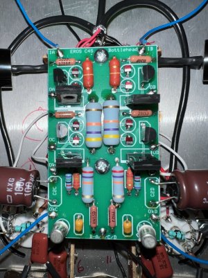
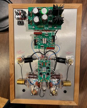
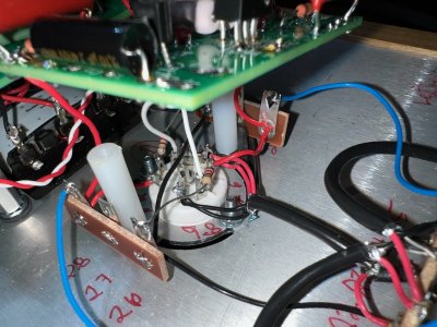
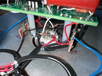
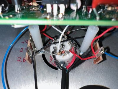
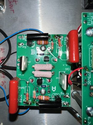
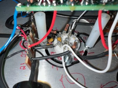
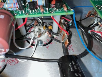
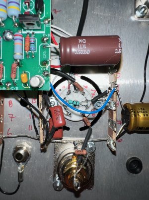
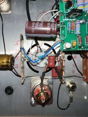
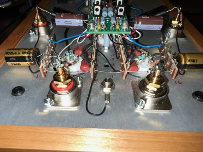
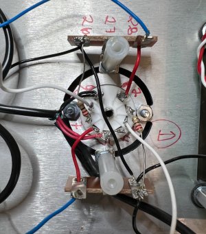
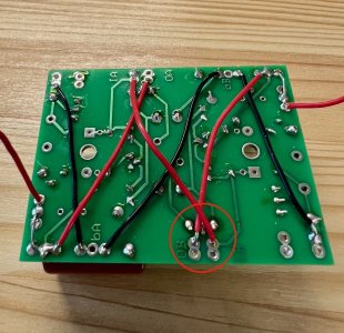
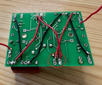
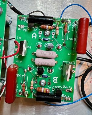
I am assuming that the issue is with the shunt board or D socket, but would appreciate your thoughts. I walked away from the project for a couple of months and got the Eros back out today to take some pictures, which I will post shortly.
Thanks much,
Darren
After building and installing the shunt board, I did the voltage check and passed (I don't recall the actual measurements, it's been a while). I then proceeded through the rest of the build, passed final the resistance test, but failed the final voltage check on the C4S board. The B side of the board was fine, but all the values on the A side were off (If I recall correctly, they were low - apologies, but I did not write the actual values down at the time). I double-checked all the solder joints and connections on the C4S and A,B, and C sockets and they looked solid to me.
I found a couple of posts here where users had similar issues and Paul's advice was to remove the blue wires from IA and IB on the C4S and re-check the shunt board. I did that and got the following readings on the shunt board:
OA: 283
OB: 210
BREG A: 283
BREG B: 210
KREG A: 6.42
KREG B: 2.83
I was confused that I now had higher values on the A side, but went back and reflowed the solder joints on the D Socket and some that I thought might be problematic on the shunt board and terminal lugs, measured again and got the following values:
OA: 273
OB: 207
BREG A: 273
BREG B: 207
KREG A: 6.5
KREG B: 2.84
I read another post where Paul or Doc advised someone whose measurements were off to try going through the rest of the build to see if they evened out after doing the C4S Board. This obviously differs from my scenario but I tried hooking up the blue wire to IA and IB on the C4S again (hoping this wasn't a mistake), tested and passed the resistance test, and tried the voltage check again:
IA: 140
IB: 159
OA: 138
OB: 157
OC: 97
OD: 96
OKA: 97
OKB: 97
OKC: 1.76
OKD: 1.61
With the C4S connected, the measurements on the shunt board were:
OA: 161
OB: 140
BREG A: 161
BREG B: 140
KREG A: 3.73
KREG B: 2.63
I am assuming that the issue is with the shunt board or D socket, but would appreciate your thoughts. I walked away from the project for a couple of months and got the Eros back out today to take some pictures, which I will post shortly.
Thanks much,
Darren
") .
.