Eros - Shunt Regulator Voltage Test

onion_breath

New member
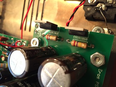
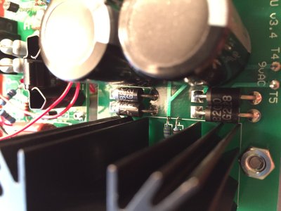
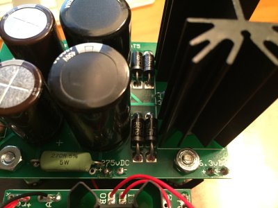
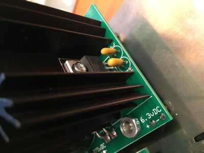
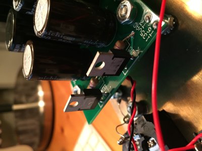
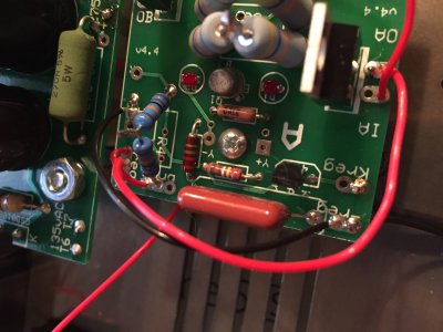
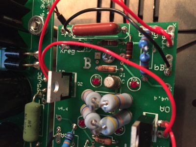
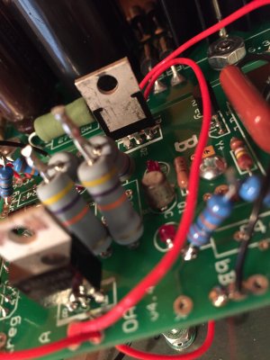
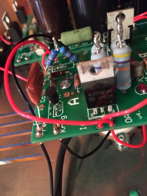
I've been putting together my Eros kit over the past few days and have now reached the Shunt Regulator Voltage test. So far kit has been going fine, but I am getting measurements that are far from what is expected.

All four of my LEDs on the Shunt Regulator are lighting up and the tube is currently glowing. I'm not sure if the tube could be the problem - all of the tubes I've received have very faint lettering on them so it's hard to determine which is which. I put what I thought was the 12bh7 in the socket (tallest tube out of the lot assigned to this kit), but maybe thats the 6DJ8 (i don't think it's the EF86 tubes since those are the only ones that match).

My measurements for the D1 teflon wire is 4.873 V DC. The D6 teflon wire read 3.3356 V DC.

Any insight would be greatly appreciated. Also, if there's any other measurements needed or even photos to add in aiding me I am all for it.

Thanks,
Greg
 
The best way to get help from the Bottlehead team is to post all out of spec voltages with the terminal number and value. Post pictures too since that's helpful for troubleshooting remotely.
 
No problem. Individual triode variations will make the hybrid regulator tube cathodes (pins 3 and 8 of the 12BH7) vary quite a bit. The voltage must be at least 2.5v for the 431 chip to work properly, and a voltage over 36v will damage the chip. As long as the other voltages are within spec, you should have no problems.
 
Hi Paul,

Just so I'm understanding correctly - the Shunt Regulator Voltage test is expecting the readings on D1 and D6 to peak above 300 VDC and drop to about 225 VDC, but the readings I received on D1 ( 4.873 VDC) and D6 (3.3356 VDC) are seemingly lower than what's expected. So these readings aren't an issue? I just want to know before moving forward with the next set of instructions, since there's nothing on page 58 of the manual mentioning readings this low.

Thanks again,
Greg
 
I'm guessing PJ misread your post and thought you were listing cathode voltages rather than plate voltages. You are correct that those plate pins D1 and D6 should read 225V volts. Check your PC board over for missed solder joints and misplaced components. Posting a good closeup picture of the board here will give us an opportunity to help try to spot any errors.
 
Thanks for for response. I went ahead and reheated a solder point on one of the 1N5820 rectifiers that looked liked it needed a touch up. Attached are the best photos I could take at the moment. Let me know if there's any other photos I can take to make troubleshooting easier.

Thanks in advance
 

Attachments

  • IMG_0081.JPG
    IMG_0081.JPG
    1.7 MB · Views: 41
  • IMG_0082.JPG
    IMG_0082.JPG
    1.1 MB · Views: 24
  • IMG_0083.JPG
    IMG_0083.JPG
    1.1 MB · Views: 27
  • IMG_0084.JPG
    IMG_0084.JPG
    472.2 KB · Views: 25
  • IMG_0085.JPG
    IMG_0085.JPG
    1.2 MB · Views: 26
Since the problem is associated with the shunt reg PC board that is installed on the D socket, close up photos of that board were actually what I was asking for, rather than the power supply board.
 
If you have adequate voltage at IA and IB (In other words, measure the high voltage output of your power supply board in addition to what you're measuring now), and almost no voltage at OA and OB (which go to D1 and D6), then you very likely have inadequately soldered the center legs of the MJE5731 transistors.  I am guessing this is at the heart of your problem since the LED's are lit up.

If you measure the output of the power supply board and it's very low, then there's likely a short that's dragging everything down.

A bad tube at the D socket will generally give very high voltage at D1 and D6.
 
I was finally able to get some time to go through your suggestions and here's what I was able to measure.

IA 336.3
IB 337.1

OA 3.18
OB 4.87

output power supply board 6.31

I reheated and re-soldered all the legs of both MJE5731 transistors and checked for any other bad solder joints while I had the iron hot. I'll also attach a few photos of the shut reg PC board.
 
Here are the photos. If you need more detail I can try and post with some better lighting.
 

Attachments

  • IMG_0086.JPG
    IMG_0086.JPG
    1.2 MB · Views: 46
  • IMG_0087.JPG
    IMG_0087.JPG
    1.3 MB · Views: 38
  • IMG_0088.JPG
    IMG_0088.JPG
    1.3 MB · Views: 32
  • IMG_0089.JPG
    IMG_0089.JPG
    1.4 MB · Views: 38
Pull the 12BH7 and remeasure IA and OA.

You don't appear to have a short behind the C4S, which is a good thing, but something at the output of the C4S is yanking down your regulated voltage.  Do also check that you have LM431's or TL431's in the 431 slot, as sometimes MPS4250's can be installed accidentally since they look the same (though this usually produces a different set of symptoms).

-PB
 
Checked the 431 slot which had 431's installed properly. Pulled the 12BH7 and measured IA and OA. IA read: 352.2 VDC ; OA read: 4.78 VDC.

 
If there are any other measurements needed to help troubleshoot, or anything else recommended please let me know.

I'll just be putting the build on hold in the meantime.
 
Are all of the jumpers on the board showing good continuity from pad to pad?
 
Remove the red wire from OA that connects to the tube socket.  Also remove the red wire from OB that connects to the tube socket.

Now recheck OA and OB.

-PB
 
I removed the red cable from both OA and OB.

OA : 4.79 VDC
OB : 4.89 VDC

I also remeasured IA and IB.

IA : 360 VDC
IB : 360 VDC

I'll see what recommendations you have, and will try to work on more troubleshooting tonight.

 
Back
Top