Eros 2 Strange Terminal Voltage readings

kjwcb2

New member
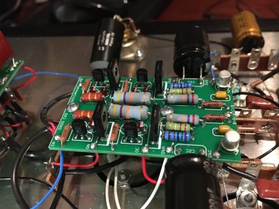
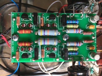
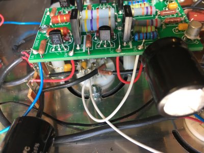
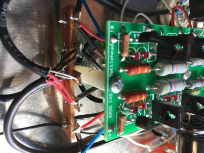
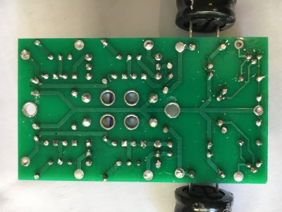
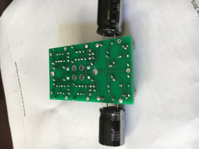
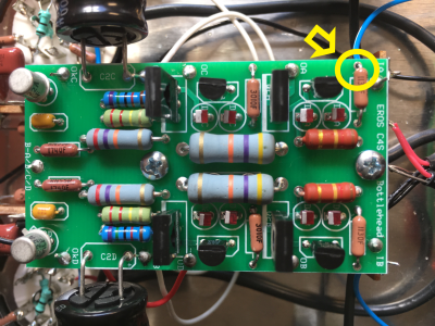
Hi, Can anyone suggest what might be a likely cause of the wrong readings listed below before I start dismantling/re-soldering etc? They are all on one side of the C4S board.

Terminal Voltage (DC)
IA 210-230V  221.5
IB 210-230V  220.7
OA 155-185V 218.4
OB 155-185V  160.4
OC 95-100V 60.03
OD 95-100V  95.7
OkA 95-105V  64.4
OkB 95-105V  96.5
OkC 0.7-2V  2.4
OkD 0.7-2V  1.32

Thank you!


Hi Paul, Attached are some photos. Are they what you wanted to see?
 

Attachments

  • IMG_3613.JPG
    IMG_3613.JPG
    2.3 MB · Views: 18
  • IMG_3614.JPG
    IMG_3614.JPG
    2.6 MB · Views: 7
  • IMG_3615.JPG
    IMG_3615.JPG
    2.3 MB · Views: 5
  • IMG_3616.JPG
    IMG_3616.JPG
    2.3 MB · Views: 6
  • IMG_3617.JPG
    IMG_3617.JPG
    2.2 MB · Views: 6
  • IMG_3618.JPG
    IMG_3618.JPG
    2.8 MB · Views: 11
  • IMG_3621.JPG
    IMG_3621.JPG
    1.8 MB · Views: 18
  • IMG_3622.JPG
    IMG_3622.JPG
    1.5 MB · Views: 10
Thanks for the advice. I went back through the whole build from the completion and test of the power supply board (as the readings were fine at that point) and resoldered all components on the C4S board. During the check, I found a resistor arm that I hadn't trimmed which may well have been shorting a couple of tabs on the A socket. I strongly suspected that that might be the cause of the strange voltage readings.
Imagine my joy when I checked the C4S board again and got these readings:

IA 210-230V  221.5
IB 210-230V  220.7
OA 155-185V 158.2
OB 155-185V  160.4
OC 95-100V  99
OD 95-100V  95.7
OkA 95-105V  99
OkB 95-105V  96.5
OkC 0.7-2V  1.51
OkD 0.7-2V  1.32

BUT: I decided to recheck after a couple of minutes and was shocked to now get these readings:

IA 210-230V  2233.5
IB 210-230V  219.2
OA 155-185V 9.94
OB 155-185V  165.7
OC 95-100V  5.2
OD 95-100V  93.2
OkA 95-105V  3.37
OkB 95-105V  94.9
OkC 0.7-2V  1.54
OkD 0.7-2V  1.21

I've checked these readings again and again and they stay the same. Have I fried something? BTW, I rechecked the power supply board readings and they are now:

-/+ 6.3 gives 6.28  /  -/+275 gives 267.5. It was fine before though I can't remember the exact value.


To check for shorted transistors, set your meter to beep for continuity, then check each pair of transistor leads on each transistor on that board.  If any two leads are shorted together, the transistor is blown.
 
kjwcb2 said:
I went back through the whole build from the completion and test of the power supply board (as the readings were fine at that point) and resoldered all components on the C4S board.

Did you get the outside resistor leg near IA that grufti pointed out? I'd solder it from the topside. See circled in attached pic.

cheers, Derek
 

Attachments

  • IMG_3614_resized.png
    IMG_3614_resized.png
    3.6 MB · Views: 21
Thanks for your continued help guys. So, yes, I've filled the outside resistor leg hole near IA that grufti pointed out and the transistors aren't blown - I tested them multiple times. Interestingly, the 100mF/160V capacitor on the 1A side of the board gives a continuity beep, where the equivalent cap on the other side of the board does not. Could that be the problem? As you can understand, I'm no expert on electronics.
 
kjwcb2 said:
Interestingly, the 100mF/160V capacitor on the 1A side of the board gives a continuity beep, where the equivalent cap on the other side of the board does not. Could that be the problem? As you can understand, I'm no expert on electronics.
Is this with the board still wired up? 

This could indeed be an issue, but it's a 1 in 1,000,000+ chance that the cap is just randomly bad.  It's more likely that there's a miswire between the board and where it connects into the preamp, or an issue with a different component on the board.
 
Yes, that's with the board still wired up. I've gone over the wiring connects between the board and the rest of the preamp and it all seems perfect. The bad readings are on the 1A side of the board so does that mean it could be one of the other components on that side?
I'm thinking of asking Bottlehead to send me all the components for the C4S board and build it again from scratch.
 
If you have the + side of that capacitor wired to pin 9 of the middle socket instead of pin 8 (presuming it's that side), then you would get a continuity beep as well.
 
Back
Top