CrackSB worked fine for one year till now. Need help troubleshooting [resolved]

deltaray

New member
My Crack+SB has been working fine over the past year with many tube rolling adventures.

However one evening I came across large popping sounds in both channels before leaving channel imbalance with weak to no sound on the Right channel.

Everytime I power it on now starts with popping sounds, followed with weak and gradually fading sound on the right.

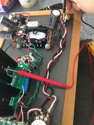
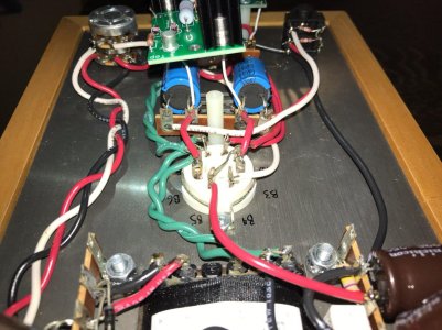
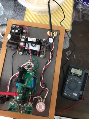
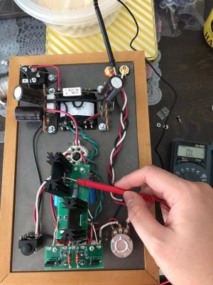
These are the current Voltage reading after doing a reheating of the solder links:
OA: 50.9V
OB: 80.5V
G: 1.9mV
B+: 97.3V

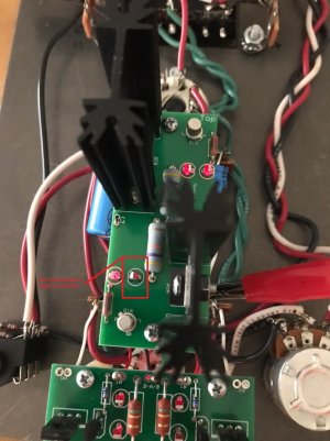
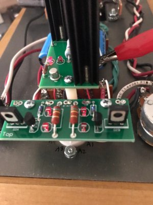
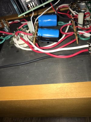
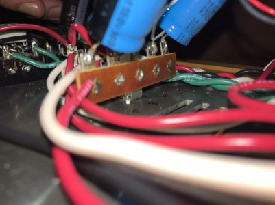
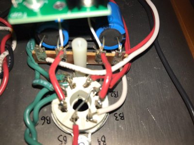
I'm attaching pictures showing the led lights, noticed that 01 at R2A doesn't shine as bright as the rest anymore..

The amp was working fine with no imbalance, capable of driving my 600ohm dt880 to deafening levels. So am definitely bummed out it can't work now, just that i'm not sure what is wrong/to check.

Any guidance is greatly appreciated  :).
 

Attachments

  • 01 at R2A.jpg
    01 at R2A.jpg
    275.9 KB · Views: 19
  • others 1.jpg
    others 1.jpg
    149.9 KB · Views: 17
  • others 2.jpg
    others 2.jpg
    119.3 KB · Views: 17
Can you remove the 6080 tube and run the amp with just the 12AU7 tube and measure the voltages on the small PC board?  It will help to start there to know that those are OK.

If B+ is down around 90V, you need to not run the amp for very long, as the power supply dropping resistors are going to get hot pretty quickly.  Try to limit your time powered up to about a minute. 
 
Greatly appreciate the help Paul :)

Measurements of the small PC board with only 12au7 tube are as follows:
OA: 78.9V
IA: 242V
B-A/B 0.1mV
IB: 242.1V
OB: 80.8V
 
OK, that's helpful.

With the amp off, clip one probe onto a ground terminal (I like the little bit of bare wire between the ground tabs on the RCA input jacks) and measure the DC resistance to the metal tab on each TIP50C.

Your measurements with and without a 6080 point to one of the TIP50 transistors touching its heatsink.  This can happen from debris sneaking in there, or if the shoulder washer or mica insulator aren't properly positioned.
 
Both metal tabs read 0 ohms. do i try to clean the insulator in between the heatsink and the tip50? both parts are soldered onto the board already
 
Is this correct?
 

Attachments

  • photo_2019-12-02_22-05-24.jpg
    photo_2019-12-02_22-05-24.jpg
    195.2 KB · Views: 22
  • photo_2019-12-02_22-05-25.jpg
    photo_2019-12-02_22-05-25.jpg
    200.8 KB · Views: 20
I would remove the hardware from both TIP50s and bend them away from the heatsinks, then recheck the resistance between ground and the metal of the TIP50s.
 
Is this correct? Both metal parts of the TIP50s read zero.
 

Attachments

  • photo_2019-12-03_09-41-58.jpg
    photo_2019-12-03_09-41-58.jpg
    170.7 KB · Views: 14
OK, so it's not an insulation issue.  Can you pull the 6080 and recheck those resistances?  If they are still 0, then can you unscrew the big PC board and post a photo of terminals 6-10?
 
Resistances still zero.

Here are the pics of 6-10. Do let me know if i need to retake clearer shots.
 

Attachments

  • photo_2019-12-03_21-26-24.jpg
    photo_2019-12-03_21-26-24.jpg
    186.8 KB · Views: 11
  • photo_2019-12-03_21-26-23.jpg
    photo_2019-12-03_21-26-23.jpg
    115.5 KB · Views: 7
  • photo_2019-12-03_21-26-26.jpg
    photo_2019-12-03_21-26-26.jpg
    168.6 KB · Views: 8
  • photo_2019-12-03_21-26-25.jpg
    photo_2019-12-03_21-26-25.jpg
    191.2 KB · Views: 13
OK, I don't see issues around the socket.

Remove just the white wires from the big PC board, then recheck those TIP50 metal tab resistances once more.

-PB
 
Finally managed to squeeze in time to do the solder removal to take out those joints.

Yes both resistance shows zero as well.

Could it be that the LED itself is spoilt?
 

Attachments

  • photo_2019-12-08_11-26-58.jpg
    photo_2019-12-08_11-26-58.jpg
    188 KB · Views: 14
  • photo_2019-12-08_11-27-02.jpg
    photo_2019-12-08_11-27-02.jpg
    179 KB · Views: 13
Put it all back together, paying special attention to how the TIP50s are mounted so that the metal tabs don't touch the heatsinks, then recheck the resistances on terminals 1-10.  We may have been chasing absolutely nothing this whole time.
 
Alright, have put it back together.

Find below the resistance measurements (from 12U):
1: 14 MΩ
2: 8 MΩ
3: Zero
4: 15 MΩ
5: 15 MΩ

6: 2.5 KΩ
7: OL
8: Zero
9: OL
10: 2.5 KΩ
 
OK, those are OK resistances, so now we are back to repeating the voltage checks, being careful to turn the amp off if B+/2/4 dip down below 100V.
 
Back
Top