Crack build, silver wire, comments?

AllanMarcus

New member
Hello,

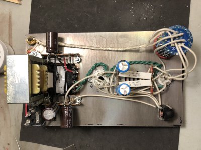
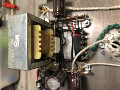
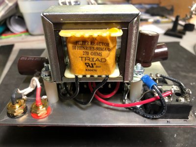
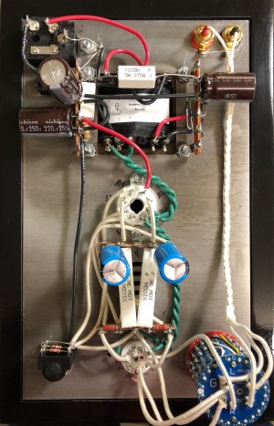
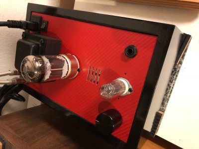
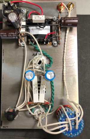
I recently finished my basic build of my second Crack. For this Crack I replaced all the signal path wire (I think) with 24AWG solid core, 99.99% silver wire (because I had some). The silver wire is sleeved in cotton, and mostly covered in clear heat shrink. I also upgraded the pot with a stepped attenuator.

I'm looking for comments on the signal path. I tried to follow some other threads on the same topic here, but none were definitive. Also, will I regret using 24AWG wire? It's what I had. I wasn't married to silver wire, but I had it, so what the heck.

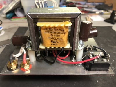
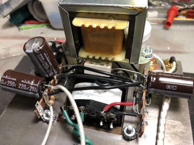
I will add the speedball next, then a choke.

Thanks,

Allan
 

Attachments

  • crack-silver.jpg
    crack-silver.jpg
    2.3 MB · Views: 116
  • crack-silver-top.jpg
    crack-silver-top.jpg
    1.8 MB · Views: 54
You pretty much got all the signal path. You might replace the black wire going from the headphone jack to the filter cap terminal.
 
Thanks Doc! I'll do that when I do the speedball.

I'm always amazed at how great the crack sounds. I'm really looking forward to the Mainline. Plus, my wife is tired of me talking about how I'm going in the garage to play with my crack.
 
The red wire from the power supply to the octal socket is also technically in the signal path.

24AWG wire is plenty big for everything except the wiring done by the 18AWG green twisted wires.

-PB
 
Thanks Kitchener.

I upgraded the last two wires, as suggested. I drilled the holes for the choke, but it's getting late, so choke will come tomorrow.


Attachments

  • crack_wiring_revised.JPG
    crack_wiring_revised.JPG
    2.1 MB · Views: 55
I’ve just had my Crack for a week now and I love it dearly.
But I have a problem; I’m itching to tinker with it!
I’m suffering from the same (French accent) ‘ow you say...petit mort (end of French accent) as after building my keyboards.
I’m already eyeing the Speedball with lustful eyes.

What attenuator did you use?
Did you have to modify the pot hole to fit it?

What choke are you planning on fitting?
 
I got the attenuator years ago. Not sure which one. I've used an alps blue velvet pot, and it works very well, but it's a bit of a pain to solder unless you can find a version with lugs. I'm not sure I like the steps on the attenuator. It's only 23 steps. Even though the resistance based attenuator is "better" than the Blue Velvet "pot", the smooth control of pot has its advantages. And yes, I had to modify the hole.

As for the choke, It's done! I used a Triad choke from Mouser
https://www.mouser.com/ProductDetail/553-C7X?r=553-C7X

The hard part was making absolutely sure I was drilling in the right place. I drilled a tad to close to the transformer for one hole, so I had to use a file to "move" the hole a bit away. Not tragic, but it took some extra time. I used 1' nylon spacers. I still need to ground the choke.

Any comments on how I ran the wires from the choke to 13 & 15?

Do I hear a difference? Who knows. Unless I can A/B, I can't tell. I'm just gonna believe it sounds better :-)


Attachments

  • IMG_0031.JPG
    IMG_0031.JPG
    3.7 MB · Views: 43
  • IMG_0032.JPG
    IMG_0032.JPG
    2.8 MB · Views: 28
  • IMG_0033.JPG
    IMG_0033.JPG
    2.7 MB · Views: 29
  • IMG_0034.JPG
    IMG_0034.JPG
    3.1 MB · Views: 27
The attenuator is probably a Valab 23. Here's a link to some on eBay
https://www.ebay.com/sch/i.html?_from=R40&_trksid=p2047675.m570.l1313.TR0.TRC0.H0.XValab+23+Step+Ladder+Type+Attenuator.TRS5&_nkw=Valab+23+Step+Ladder+Type+Attenuator&_sacat=0

And here is the chock grounded...
 

Attachments

  • IMG_0036.JPG
    IMG_0036.JPG
    2 MB · Views: 35
Just a recommendation for the future, use metal standoffs to ground the choke (only one needed, but two looks better).  Makes things less cluttered.
 
Leland Hankins said:
Just a recommendation for the future, use metal standoffs to ground the choke (only one needed, but two looks better).  Makes things less cluttered.

Thanks. I had some metal standoffs just a weeks before I decided to add a choke, but I got rid of them with another project thinking I had no need for metal standoffs! They I went to my local hardware store, which has everything, but they didn't have standoffs. I thought  about using zinc spacers, but wasn't sure, so I got nylon. I figured I could just add the ground wire.

Just goes to show ya: never throw anything away or get rid of anything! :-)

Someone on SBAF asked why braid the wire between the inputs in the pot. I said EMI/RFI rejection, but another guy that sounds like he knows what he's talking about, said twisting the wires (like the heater wires) is good for rejection, but braiding less so. Why do we braid the wires? Is it just for wire management?
 
Both braiding and twisting provide some immunity to magnetic and electric fields. If you ask which is better, you enter the territory of second-order effects, which requires a greater knowledge of the exact circumstances including the specific interfering noise source.

In some applications we use CAT-5 type cables which have individually shielded twisted pairs which are contained within an overall shield as well. That's probably an improvement in a majority of circumstances, but not all.
 
Back
Top