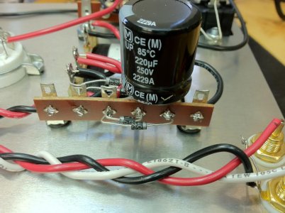
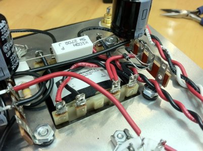
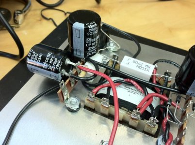
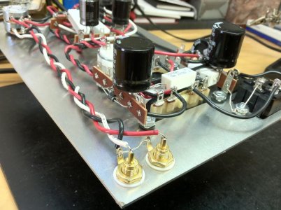
Hi, brand new builder here. No real electronics knowledge but can follow directions and solder. I bought a Crack kit back in 2013, life got in the way but after nearly four years I finally got around to building it over the past couple days. After completing the build and visually inspecting it for quite awhile I was confident that everything was where it is was supposed to be in the correct orientation. I moved onto the testing.
Resistance checks were close to perfect. Terminals with * were fluctuating similarly. Terminals expecting 2.4K read 2.48K. Terminals expecting 2.9K read 2.94. RCA jack grounds 0. RCA Jack Center Pin were both between 90K-100K.
So, I went to the next stage and powered it up. Tube filaments were glowing. I took Voltage measurements...but didn't write these down as everything was reading quite close to the expected voltages. Certainly within 10%.
Except for B1. Manual says this should read 90 but it was reading 145. I made a note of that.
I went ahead and performed the Final Check at the TRS jack and it climbed up to 9V and then dropped to zero.
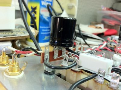
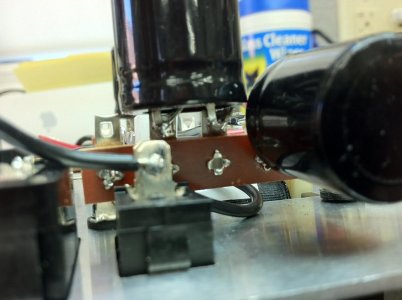
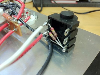
I retraced the wiring and checked the orientation again and it all checked out. I trimmed up a couple spots where wire was sticking out a bit. I found one wire that wasn't properly soldered on the TRS jack. I re soldered B1 along with where the wire from it attaches at the Terminal. I re soldered at the IEC and a couple spots on the transformer.
Went through the resistance measurements again and they were once again almost perfect. Powered it up to take voltage measurements but the tubes didn't light up. Powered it off and checked the fuse, it was blown? Today I picked up a couple replacement 500ma fuses. Each time I powered it on, the fuse immediately blew.
I've been searching through this site and read that blown fuses might indicate blown rectifier diode. I don't really know enough about testing them, but read the manual of my DMM and it has a Diode mode. I took readings of them, from one orientation of the probes it would read .45V and with the probes reversed it would read 0L. This was the same with all four of the rectifier diodes. I don't know what that means.
I don't know what else to do at this point? I've read most problems are the result of a bad solder joint. But would bad solder joints cause the fuses to blow? I've also read on the forum that the crack uses 1 amp fuses now. My kit came with 500ma fuse. Should I try 1 amp fuses?
Any help would be greatly appreciated.
Many thanks!
Resistance checks were close to perfect. Terminals with * were fluctuating similarly. Terminals expecting 2.4K read 2.48K. Terminals expecting 2.9K read 2.94. RCA jack grounds 0. RCA Jack Center Pin were both between 90K-100K.
So, I went to the next stage and powered it up. Tube filaments were glowing. I took Voltage measurements...but didn't write these down as everything was reading quite close to the expected voltages. Certainly within 10%.
Except for B1. Manual says this should read 90 but it was reading 145. I made a note of that.
I went ahead and performed the Final Check at the TRS jack and it climbed up to 9V and then dropped to zero.
I retraced the wiring and checked the orientation again and it all checked out. I trimmed up a couple spots where wire was sticking out a bit. I found one wire that wasn't properly soldered on the TRS jack. I re soldered B1 along with where the wire from it attaches at the Terminal. I re soldered at the IEC and a couple spots on the transformer.
Went through the resistance measurements again and they were once again almost perfect. Powered it up to take voltage measurements but the tubes didn't light up. Powered it off and checked the fuse, it was blown? Today I picked up a couple replacement 500ma fuses. Each time I powered it on, the fuse immediately blew.
I've been searching through this site and read that blown fuses might indicate blown rectifier diode. I don't really know enough about testing them, but read the manual of my DMM and it has a Diode mode. I took readings of them, from one orientation of the probes it would read .45V and with the probes reversed it would read 0L. This was the same with all four of the rectifier diodes. I don't know what that means.
I don't know what else to do at this point? I've read most problems are the result of a bad solder joint. But would bad solder joints cause the fuses to blow? I've also read on the forum that the crack uses 1 amp fuses now. My kit came with 500ma fuse. Should I try 1 amp fuses?
Any help would be greatly appreciated.
Many thanks!