Strikkflypilot
New member
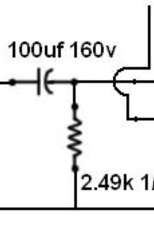
If I am not completely wrong, the coupling caps e.g. in the Crack is part of a highpass filter on the output. The other part is the 2.49kohm resistor on the jack?
So if I want to keep the cutoff frequency and swap out the cap for a slightly larger or smaller one, I could if I also change the jack resistor, thus keeping the corner frequency but altering output impedance and time constant?
So if I want to keep the cutoff frequency and swap out the cap for a slightly larger or smaller one, I could if I also change the jack resistor, thus keeping the corner frequency but altering output impedance and time constant?
")