Copper-clad S.E.X. build

JeffYoung

New member
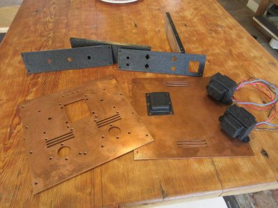
Being not generally a fan of the "top plate" style of amplifier, I'm constructing some custom casework for my S.E.X.


Top and bottom are 2mm copper plate, machined and then pickled in vinegar & salt and baked for 5 min at 450º.  Since the connectors & controls are on the front and back, I've gone for a square plan (250mm x 250mm), which also gives me a bit more width to fit some bigger caps under the hood.


Sides are 1/2" x 2-1/2" aluminium bar; front and back are 0.090" aluminium plate.  The front, back and sides are inset about 1/16" to give a bit of an "ice-cream sandwich" look.  (In hindsight I think 1/8" or 3/16" inset would have looked better.)


The holes in the back might look a little odd: I've switched out the speaker posts for some vintage-style ones to go with the casework better.  Same for the front: the power switch is rotary (with a chicken-head knob), while the volume pot is an Alps with a big Dakaware knob. 


Front, back, sides, output chokes and transformer bell painted in wrinkle-finish paint.


Attachments

  • casework.JPG
    casework.JPG
    68 KB · Views: 174
Looking forward to seeing the finished product. Please include build photos too, always nice to see someone's vision come to life.
 
I've got a bit more done, but I didn't take any pictures yet.

I'm upgrading the interstage and parafeed caps, so I decided to make use of the little Dayton 0.1uF's by putting snubbers on the two transformer secondaries.  I used Quasimodo (http://www.diyaudio.com/forums/power-supplies/243100-simple-math-transformer-snubber-using-quasimodo-test-jig.html) to stimulate ringing in the transformer secondaries and came up with the following CRC networks to more-or-less critically dampen them:

Filament secondary
Cx: 0.01uF Illinois 220VAC polyester
Cs: 0.1uF Dayton 400VDC polypropylene
Rs: 8 - 10 ohms

B+ secondary
Cx: 0.01uF Illinois 220VAC polyester
Cs: 0.1uF Dayton 400VDC polypropylene
Rs: ~ 400 ohms

Cheers,
Jeff.
 
The shielded twisted pair that we provide with the kit may offer lower noise than just a twisted pair of cables.

Also, the 0.1 Ohm 5W resistor provided is not in the signal path and does not benefit from being replaced with a different part.
 
Hi Paul,

The bulk of my changes are just about looks.  I like the look of the Ohmites, so I'll also be using them in the CRC filter for the B+ supply.  8)

Same for the twisted pair heater wiring.  I figured I could get away with it on a DC heater, and the twisted pair is easier to keep at 90º to the signal components (which will hopefully mitigate any noise issues).

Another set of changes is just to match my "house" style: I'll be separating the signal ground from the chassis ground, and I'm using the same wire colours as in my other builds.

I am making a few changes for sound: larger caps in the CRC filter (with the last stage bypassed by film caps) and upgraded interstage and parafeed caps.

Cheers,
Jeff.


PS: I don't kid myself that the transformer snubbers are likely to improve the sound either.  But they might, and they were fun to research and implement.


I'll be separating the signal ground from the chassis ground,

They need to be connected somewhere, as well as the power supply ground.
 
Doc B. said:
They need to be connected somewhere, as well as the power supply ground.


Yep; no worries.  The chassis will be connected directly to the IEC ground, while the signal ground will be connected via opposing 600V 35A diodes and a 680V 8A thermistor.


Cheers,
Jeff.
 
Hi Paul,

The same discussion was had over on DIYAudio forums, but no one ever gave a good reason why (other than that a wire was "safer").

If anything over 1.1V leaks to the signal ground then those diodes are going to look like a wire plenty long enough to vaporise the IEC fuse (or trip the residual-current-detector).  And if there should be some failure mode that presents less than 1.1V with high current, that thermistor won't even be warm before the fuse meets the same fate (or the RCD goes).

I can understand if the failure mode of diodes + thermistor has more to do with lawyers than electricity, in which case no more needs be said.

But if there's some other failure mode of the diodes + thermistor approach I'd love to hear it.

Thanks,
Jeff.
 
Yes, the wire is safer. 

You're adding parts to a proven design to solve a problem that you do not have, that's the core issue. 
 
At the risk of giving the Pauls a heart-attack, here's another picture of my S.E.X. developing.


Note that this build uses non-standard wiring and component positions.  Don't follow this as a guide.

You can see several changes here (after all, the middle initial is for "experimenters"):
  • I've added CRC snubbers to the B+ supply.  (http://www.hagtech.com/pdf/snubber.pdf)
  • I've changed the filament supply filter from an RC to a CRC.
  • More of those Ohmite resistors.
  • A Mundorf EVO al/oil for the interstage cap.


Attachments

  • right channel1.JPG
    right channel1.JPG
    135.4 KB · Views: 119
JeffYoung said:
At the risk of giving the Pauls a heart-attack
I've changed the filament supply filter from an RC to a CRC
e4db02b9-eec5-451a-859c-d9bae0aebedc-large16x9_transformer.jpg

 
You can simulate the AC current that the transformer sees with the resistor input filter and the cap input filter in PSUD.

In one scenario, the transformer runs within its specifications for temperature rise.  In the other situation, the transformer runs over its specifications for temperature rise. 

Inrush current is very brief and not generally concerning, especially with solid state rectifiers.
 
Yeah, that's why I was building a model of it in PSUD2.  The numbers don't change much: peak current goes from 6.4A to 7.1A, while RMS goes from 2.2A to 2.3A.


The temp rise in a transformer is going to track RMS, rather than peak, right?

 
Back
Top