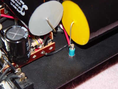
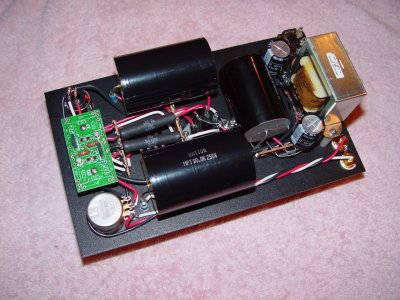
Choke specs for the Crack

JamieMcC

New member
I am considering whether to do the 12au7 choke mod on my crack and replace the last electrolytic capacitor with a film one.

Looking around at what 12au7 chokes are on offer I noticed there is quiet a difference in specs and prices.

Is there generally a favoured type re materials & performance specs brand etc that I should look out for when considering. I am guessing all chokes are not created equal even though they may look similar and marketed as the same?
 
Are you going to put a choke in the power supply or as the plate load for the 12AU7?

If in the power supply the Triad C7-X is often used.
 
Thanks that was handy I entered the Triad C7-X in the search box and found a useful thread on the topic. I belive the mod is replacing the resistor on the last cap in the power supply with the choke this would enable the Electrolytic cap 220uf to be replace with film cap uf? from my reading I picked up 4x 50uf F&T film caps the other day for not much money and thought I might try them in this configuration. I use sen HD650 and Beyer T1 so 300ohm & 600ohm impedance thought about trying them configured as 100uf-150uf-200uf it would be relatively easy and a bit of a exercise in how the sound is effected with differing values.

http://bottlehead.com/smf/index.php/topic,3498.msg30912.html#msg30912

Edit I'm thinking paralleling them up to achieve the different uf values will be fine?
 
It is my understanding that if you replace the final cap with a film you need not use the same value, uF.  So a 100uF or 150uF film will be a good replacement for a 220uF electrolytic.
 
Jamie, you could have hours of fun playing with this http://www.duncanamps.com/psud2/ comparing the resistor to choke, different cap values, and see what effect each one has.  I learnt a lot from it when building the supply for my AC quickie as some of the results were not at all obvious.  Sometimes adding more capacitance actually made things worse, and using the simulator i was able to work out optimum ranges of capacitance and resistance for each position for a given load.  Its a bit of a black art and i dont pretend to understand the math or theory behind the half of it, but it helped me cobble together a very quite and effective power supply with the exact voltage i needed at the output.
 
Mark thanks for the link I will have a play with that later and see if I can make any sense out of it.
 
Just had quick play with it, i dont have the exact details for everything but i'm estimating ~1.5mv ripple with the three 220uf caps as stock, with a C-7X choke i kept lowering the capacitance until i got back to ~1.4mv ripple and was using 220uf, 100uf, and 22uf so certainly getting into the ballpark where film caps are feasible.  Of course ripple is only one part of it, there are many other factors to consider but as far as i know film caps will be better in those areas too.  You have me thinking about the final 22uf caps in the S.E.X. supply now :)

I can post the two PSD files i made if the BH guys have no complaints, i assume there is an unwritten rule about not posting schematics or manuals bits on the internet?
 
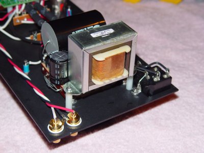
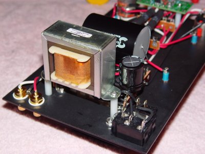
I have a Triad C7X in my 7N7 Crack.  It made a very noticeable improvement in the reduction of background noise, better low level detail and timbre.  The final PS caps are the same aluminium foil with waxed paper caps as the output.  I run 60uF output (200 ohm & 600 ohm phones) and 30uF, (actually 32.2 with K5 bypass!), for final PS.  The finals value was a trade off, better cap versus more capacitance.  Real estate made the final decision for me.

Cheers,
Geary
 
Geary, thanks for your input, am I missing anything in my assumptions that once the relevant resistor is removed the choke leads are soldered in to the same position as the resistor so effectively just a substitution all be it one that takes up more space?

Jamie
 
JamieMcC said:
Geary, thanks for your input, am I missing anything in my assumptions that once the relevant resistor is removed the choke leads are soldered in to the same position as the resistor so effectively just a substitution all be it one that takes up more space?

Jamie

Not missing a thing.... 270 ohm for 270 ohm and much more space!

Cheers,
Geary
 
galyons said:
...The finals value was a trade off, better cap versus more capacitance.  Real estate made the final decision for me.

Cheers,
Geary

LqyI9pG.jpg

vTQTH1Q.jpg
 
Super thanks this is the one I am looking at

http://www.ebay.co.uk/itm/Triad-C7X-10H-90mA-smoothing-choke-/171093411086?pt=UK_Sound_Vision_Valves_Vacuum_Tubes&hash=item27d5f6450e

$(KGrHqF,!ncFH105MFgoBR-35(0ykw~~60_58.JPG


Geary, thanks love the picture and see you have been quiet creative in installing them, nicely done by the way quiet impressive actually.

Do you like how they working out any particular strengths?  I also noticed you have not gone down the speedball route any particular reasoning behind that?

Its just interesting to hear about different approaches
 
JamieMcC said:
Do you like how they working out any particular strengths?  I also noticed you have not gone down the speedball route any particular reasoning behind that?

They are strong in imaging and timbre.  I am a PIO guy. I tried some MPP & MPP in oil, but just not to my taste.  Speedball is awaiting BH shipping.  I ran my AU7 Crack for quite awhile before doing the Speedball.  The Speedball is an improvement, but there is, to me, a trade off, better detail for less warmth.

Thanks for the kind words!

Cheers,
Geary
 
Love the double decker layout, very creative.

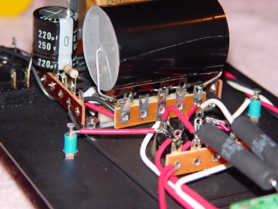
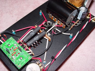
Jamie here is the idea fully implemented, i have no idea whos crack this is, its one of the many images i have saved from the gallery section before it got wiped out.
 

Attachments

  • DSC08991.jpg
    DSC08991.jpg
    121.8 KB · Views: 1,226
  • DSC08990.jpg
    DSC08990.jpg
    127.8 KB · Views: 616
  • DSC08988.jpg
    DSC08988.jpg
    138 KB · Views: 428
  • DSC08980.jpg
    DSC08980.jpg
    203 KB · Views: 471
  • DSC09006.jpg
    DSC09006.jpg
    124.5 KB · Views: 510
  • DSC09002.jpg
    DSC09002.jpg
    172.2 KB · Views: 629
Geary,

Your Crack is stuffed.  And I don't mean that in an Australian way.

I like your adaptation to mounting all the bulky upgrades too.

 
Mark thanks the pics posted really helped and saved me from making a newbie error. I had not been following correctly and had just wrongly assumed without looking at the schematic that the 270k ohm resistor which was removed was the regular shaped 1W one and not the 270 ohm 5W cement one which is sort of hidden from view. 

Looking at the schematic the second 5W 270 cement resistor is before the last 220 cap and the 270ohm 1W is after so that make is starting to make sense. If I am indeed following the schematic correctly?  Just want to be absolutely sure as the Crack is my first diy build and have no prior experience in electronics and what I have generally consider to be a black art!

Edit ah ha something be must starting to sink in that 270ohm 1W looks like it might be for draining the caps down as its after everything else?


The 1w is a 270K, thats just a bleeder across the + and - to discharge the caps on power down.  The choke replaces one of the 270ohm 5w resistors. I would have thought the first one which is over the transformer however now that i look at those pics it looks like it is installed in the second position.  I would want a bit of clarification from the BH guys on that one in case it was put there for a reason, perhaps the current or heat dissipation would be too much for the choke in that position.
 
Back
Top