C4S voltage check failing [resolved]

cacofonix

New member
Hi

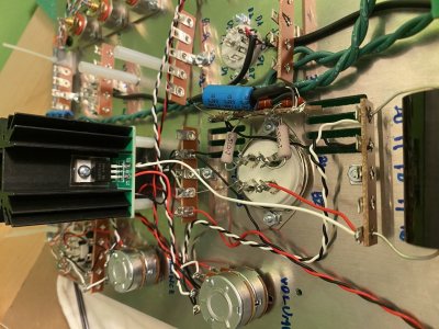
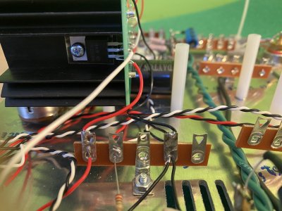
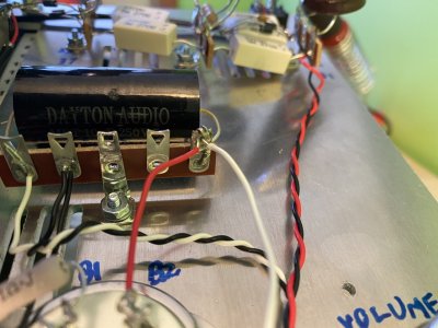
When performing the voltage checks after assembling the C4S board I get the following readings
1=151.3
11=151

6=124.1
16=148.1

I've traced through the manual steps and re-flowed the chassis connections but it hasn't addressed the high voltage on 16

Any thoughts on what might be wrong and what I could do to diagnose and rectify?

Thanks
 

Attachments

  • IMG_6913 Large.jpg
    IMG_6913 Large.jpg
    346.3 KB · Views: 10
  • IMG_6914 Large.jpg
    IMG_6914 Large.jpg
    299.7 KB · Views: 10
  • IMG_6915 Large.jpg
    IMG_6915 Large.jpg
    161.3 KB · Views: 13
I took a few more photos including of under the board, and the side with the voltage issue

Maybe it will help find the culprit


Attachments

  • Board_underside.jpg
    Board_underside.jpg
    232.1 KB · Views: 9
  • 11_Through_15.jpg
    11_Through_15.jpg
    287.8 KB · Views: 5
  • 16_Through_20.jpg
    16_Through_20.jpg
    271 KB · Views: 5
doh!

You're right @Kris - thanks for catching that.

I didn't see it even after looking at many times.

I can't wait to fix that mistake (but also scared of trying to remove and solder that diode with clipped leads)
 
cacofonix said:
but also scared of trying to remove and solder that diode with clipped leads

Yeah, I wouldn't even try to reuse that LED. They are too fragile and most likely will not survive that amount heat.
Just contact Bottlehead and order replacement.
 
Kris said:
Yeah, I wouldn't even try to reuse that LED. They are too fragile and most likely will not survive that amount heat.
Just contact Bottlehead and order replacement.

Thanks Kris. I ordered a pack of replacements

Paul Birkeland said:
I would also suggest a lot more heat and some more solder on the Q2 transistors and the R2 resistors on that board.

Thanks Paul

I was definitely tentative with the heat and the solder on the board thinking that my ham-fistedness would either damage a component or I'd create a solder bridge or something. I will apply more solder to those and turn the heat up on my soldering iron
 
You will really need your iron set at max heat to get a proper solder joint on the center leg of the MJE5731A transistors, as that is connected directly to the metal tab which is on a big heatsink. 
 
Just wanted to follow up and not leave this thread hanging.

I got my replacement leds and made the fix that Kris caught.

I also applied more heat and solder to the connections as Paul suggested.

My BeePre2 passed all voltage checks and is fully operational.

Thank you for your help
 
Back
Top