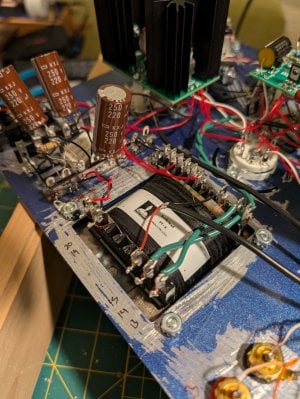
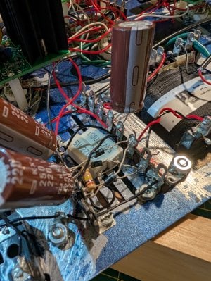
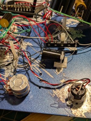
Hi - Please tell me it's not hopeless... I've built 2 Cracks w speedballs successfully and went into the crackatwoa maybe too confident. Pretty bummed out now.
I made two initial dumb mistakes:
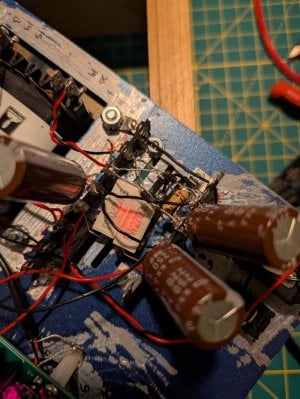
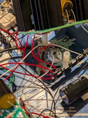
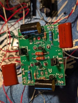
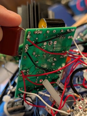
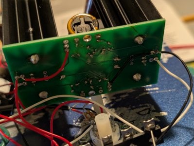
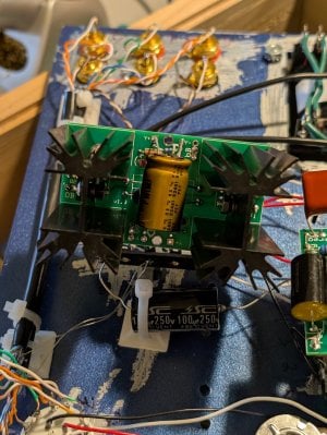
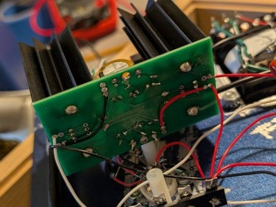
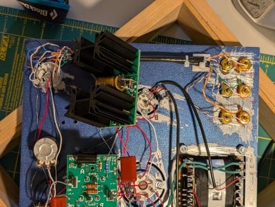
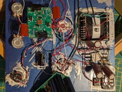
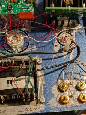
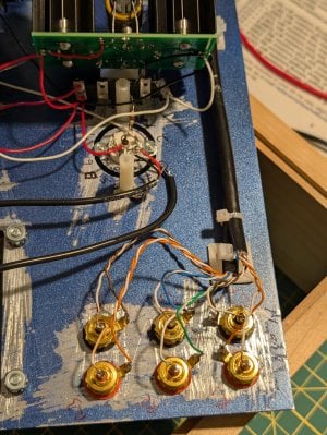
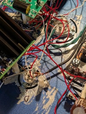
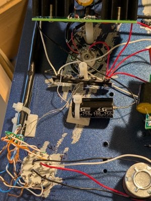
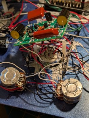
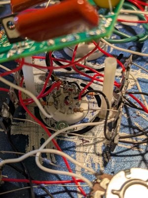
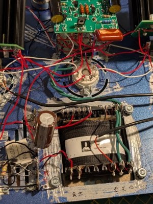
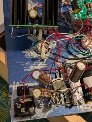
I realized the two 270Ω 5Ws were cracked from the overheating so I purchased 2 new 270Ω 5W wirewound resistors online and the leads were a bit shorter than what bottlehead provided so I soldered them together to a small black cable to connect to 32L. The pictures attached are with the new resistors.
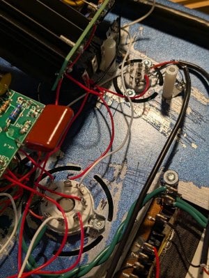
I had to pull out and reinstall all of my UF4007 rectifiers to accomplish this, so they look messy now but I triple checked they are all connected to the correct spots and in the correct direction.
After this, I went back through all C2A instructions to confirm there were no other wrong connections, and re-soldered any connections that looked poor.
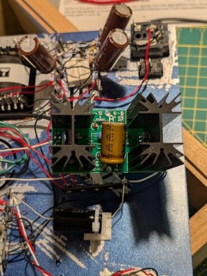
For my voltage test attempt #2, all tubes glowed and all HLMP 6000 LEDs glowed (the LEDs on the two high current boards were much brighter than the very dim LEDs on the low current board). This is when I noticed the (2) new 270Ω 5Ws started to glow orange within 10 seconds. I quickly took the picture attached before immediately unplugging the C2A.
I never got to the point to be able to do the voltage test either time.
Let me know if you have any thoughts. Thank you.
I made two initial dumb mistakes:
- I spray painted the wrong side of the chassis. Before the paint fully cured, I scraped it away down to bare metal around all of the holes and openings.
- I initially connected the (2) 270Ω 5W wirewound resistors to 33L instead of 32L.
I realized the two 270Ω 5Ws were cracked from the overheating so I purchased 2 new 270Ω 5W wirewound resistors online and the leads were a bit shorter than what bottlehead provided so I soldered them together to a small black cable to connect to 32L. The pictures attached are with the new resistors.
I had to pull out and reinstall all of my UF4007 rectifiers to accomplish this, so they look messy now but I triple checked they are all connected to the correct spots and in the correct direction.
After this, I went back through all C2A instructions to confirm there were no other wrong connections, and re-soldered any connections that looked poor.
For my voltage test attempt #2, all tubes glowed and all HLMP 6000 LEDs glowed (the LEDs on the two high current boards were much brighter than the very dim LEDs on the low current board). This is when I noticed the (2) new 270Ω 5Ws started to glow orange within 10 seconds. I quickly took the picture attached before immediately unplugging the C2A.
I never got to the point to be able to do the voltage test either time.
Let me know if you have any thoughts. Thank you.

