Blown fuse [Resolved]

tubenoob

New member
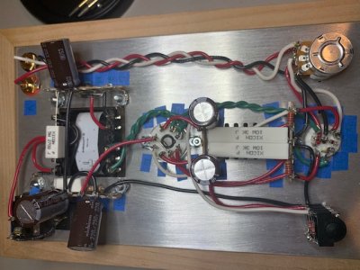
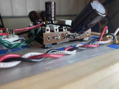
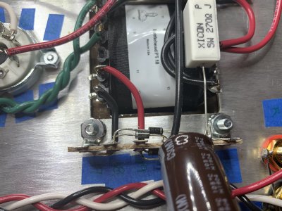
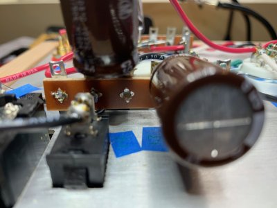
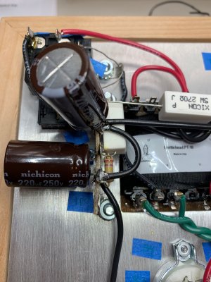
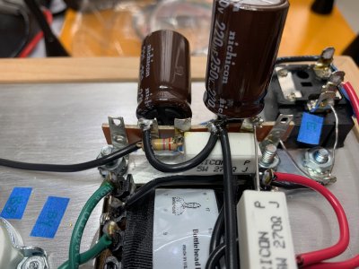
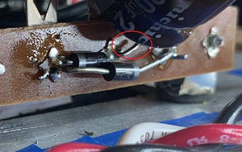
Resistance checks looked correct (see below).  Plugged in power to complete the final voltage check and immediately blew the fuse.  I'll need to purchase more fuses tomorrow if the coronavirus hasn't shut everything down by then.  I've triple checked my wiring, but could use another set of eyes as I'm not seeing any issues.  I did wind up having to replace my power switch after doing the earlier transformer, glow and voltage tests due to trying to clean up a messy solder connection on the power switch and ruining it by getting it too hot.  The previous tests (prior to the final resistance test) all checked out fine; however, again I replaced the power switch between those tests and the final voltage check. 


Resistance test results:


1. .0L

2. .0L

3. .001

4. .0L

5. .0L


6. .001

7. 2.95

8. .000

9. 2.95

10. .000


12. .000

13. .0L

14. .000


20. .000

22. .000


B3 2.95

B6 2.95


RCA Jacks

Center Pin R - 103.8 B - 97.6

Ground tab R - .000 B - .000
 

Attachments

  • IMG_1781.jpg
    IMG_1781.jpg
    103 KB · Views: 36
Could you post some close up photos of all the UF4007 diodes? 

What kind of solder was used to build the kit? (was any extra flux used?)
 
Thanks for the quick reply.  Requested pics are attached. Solder used was 60/40 lead core.  I did use flux.  Should I not have? I don't recall seeing anything in the manual advising against it, but may have missed something.
 

Attachments

  • IMG_1783.jpg
    IMG_1783.jpg
    1.4 MB · Views: 32
  • IMG_1784.jpg
    IMG_1784.jpg
    2 MB · Views: 33
Thank you for posting that.  In recent years, it has gotten somewhat more common for builders to use brazing flux or repair flux on their kits, and this flux is conductive and causes a whole ton of issues.  I could tell in your photos that some extra flux had been used, so I thought it was worth asking.  The rosin core in the solder you used is the flux, so you don't need to use any extra. 

With your black meter probe grounded, what DC resistance do you get between each end of each 270 ohm 5W resistor? 

I would also assume that all of the measurement tests before the final one were done without the fuse blowing? 

Generally what I expect when someone reports a fuse blowing immediately upon powering up a Crack is that a UF4007 diode is installed backwards, the leads of two diodes that go to two different terminals are touching, a 220uF/250V cap is installed backwards, a black ground wire is installed into an improper terminal, or a 270R/5W resistor is installed into an improper terminal.  I don't see any of this going on in your photos. 

We can split the circuit in half for the purposes of testing though.  You can remove the red wire at terminal 13 and bend it up and out of the way, then fire up the amp and see if the fuse holds (I would be surprised if the amp was suddenly happy, but it's worth the cost of the fuse to see). 

-PB
 
Thanks for helping me out with this. I’m obviously inexperienced and appreciate your patience.

Resistance seems to be all over the place when I measure the 270 ohm 5W resistors. It seems to decrease gradually during measurement and not hold

The fuse held up through all previous tests without issue.

I can try splitting the circuit as described next if you feel that’s appropriate. Thanks again.
 
No luck. Red wire @ terminal 13 removed and the fuse still blew when power was applied. I do need to note that I was only able to locate fast acting 1a fuses here locally to replace the original shipped with the kit. I have slow burn 1a ordered but they won’t be here until Thursday.
 
Can I see some close ups of the other 6 lug terminal strip (the one with terminals 11-16)?

The fuse blowing here means that something is awry on one of the 6 lug strips.  It could be an untrimmed lead poking through and touching something it shouldn't, debris, etc.
 
Well, I'm looking over everything you've posted as closely as I can.  This is all I can see that might cause that problem.
 

Attachments

  • crack mystery lead.jpg
    crack mystery lead.jpg
    288.5 KB · Views: 28
That is the lead from the UF4007 installed between 18L and 20L in the last step on page 38 of the manual.  While it's a bit long, it isn't touching anything else.  I will certainly trim it up a bit to be sure though.  At this point, should I just consider reflowing everything attached to that particular 6 lug terminal? Or both? Thanks again for the help.
 
You could remove the 270 ohm resistor that crosses over the power transformer, then try firing up the amp again.  If the fuse does hold, you will need to leave your meter leads on the 220uF cap on the terminal strip with the UF4007 diodes to discharge it, otherwise it will hold its charge and give you a tingle when you go to continue working on the circuit.
 
After discharging the capacitor and reflowing the 6 lug terminal (17-22), it WORKS!! Sounds great right away.  Can't wait for it to burn in.  Many many thanks Paul.  The help was very much appreciated!!
 
Back
Top