Big speedball board LEDs near PS in Crack will not light [resolved]

Galapac

New member
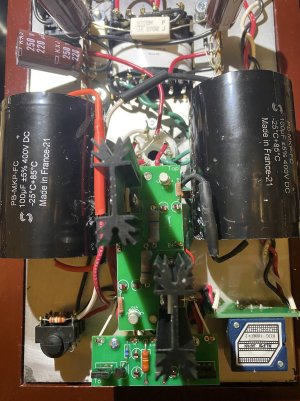
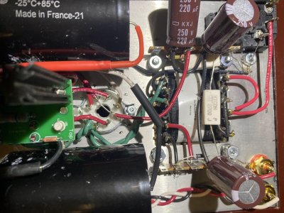
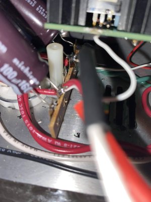
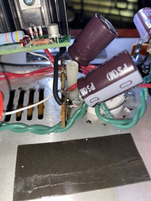
I had my BHC working for some time now and just installed 2 output film capacitors to try out the mod.
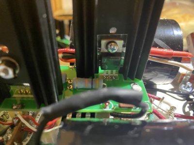
Everything was working fine until one of the capacitors disconnected from terminal 9.
Before I noticed it I had been burning in the amp and had it on for several hours and the trans was a bit hot and there was a hum in the right channel.

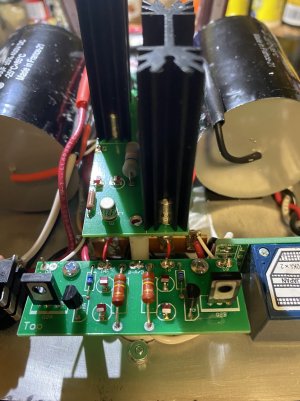
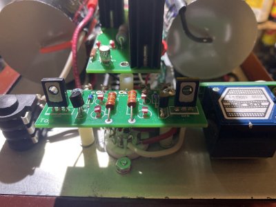
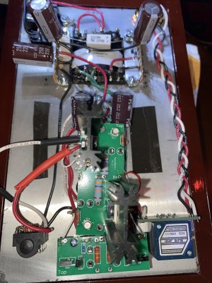
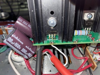
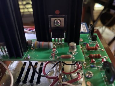
I reconnected the terminal and now the 2 LEDs nearest the power supply will not light up and I only get sound in the left channel. I rechecked my connections several times and rsolderded the OA, OB, B+, and G connections to no avail.

Small board lights up fine.

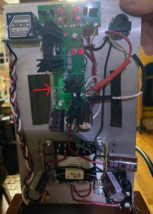
Current voltage readings from the terminals:
OA - 70.4
OB - 54.5
G - 1.9
B+ - 101

These readings appear a bit off and was wondering if anyone else had this same issue.
 
Ok, without the 6080 tube in the small board read normal ranges as follows:
OA - 71.7
IA - 228
B-A/B - 0
IB - 228
OB - 70.6
 
The most common reason to see a problem like this is that the TIP50 transistors are not properly installed on the heatsinks. If the metal tab of either TIP50 touches the heatsink, then the amp will enter the state that you have described by your voltages.
 
Paul,
I don't think it is that.
Like I said previously this was a working Crack and I just checked the TIP50 trans and both have the clear plastic between them and the heat sink.
I can share pictures if needed.
I took the board off and re soldered everything just to make sure nothing was loose and reconnected with the same issue that the 2 LEDs closest to the PS will not light and I only get music out of one channel.
Could it be that one of the new capacitors I installed has gone bad?
I checked those connections too and both are solid.
-Greg
 
Please definitely do not listen to an amp not passing its voltage checks.  This can damage your headphones.

Yes, please do post some build photos, with particular emphasis on showing the mounting of the TIP50 transistors.
 
Paul,
Let me know if you need more or of a specific area that I may not have picked up,
Greg
 

Attachments

  • IMG_0030.jpg
    IMG_0030.jpg
    298.7 KB · Views: 11
  • IMG_0031.jpg
    IMG_0031.jpg
    234.7 KB · Views: 6
  • IMG_0032.jpg
    IMG_0032.jpg
    379.5 KB · Views: 13
  • IMG_0033.jpg
    IMG_0033.jpg
    343.6 KB · Views: 8
  • IMG_0037.jpg
    IMG_0037.jpg
    409.3 KB · Views: 6
  • IMG_0038.jpg
    IMG_0038.jpg
    326 KB · Views: 5
The Q2 transistors on the big board aren't all the way soldered.

I would pull the huge caps out and retest the amp with the 6080 to see if the B+ pops up.
 
Paul,
I removed the big caps as suggested and replaced with the original caps.
I also re soldered around the TIP50 trans and re soldered the wires for OA/OB/G/B+.
Still the same result.
 

Attachments

  • IMG_0048.jpg
    IMG_0048.jpg
    267.5 KB · Views: 3
  • IMG_0047.jpg
    IMG_0047.jpg
    163 KB · Views: 2
  • IMG_0046.jpg
    IMG_0046.jpg
    228.3 KB · Views: 2
  • IMG_0045.jpg
    IMG_0045.jpg
    408.1 KB · Views: 3
  • IMG_0042.jpg
    IMG_0042.jpg
    266.8 KB · Views: 6
  • IMG_0049.jpg
    IMG_0049.jpg
    235.9 KB · Views: 3
With the amp OFF, unplugged, set your meter to test continuity (or resistance). Black probe touching heatsink on the side that is not working. Red probe to the metal tab of the TIP50 attached to that heat sink. Should read open. But if it reads shorted you will need to remove that hardware that attaches the TIP50 tab to the heatsink and inspect to figure why it is shorting.
 
I am waiting on some replacement TIP50s although they seem to test fine off the circuit.
I tested on the board touching the black terminal to the heat sink post on the underside of the board and red terminal to the collector on the screw.
One side beeped for continuity, the other was dead silent.
It is some component on this big speedball board, just not sure which component yet but the new TIP50s, once installed, I can rule out.
 
Galapac said:
One side beeped for continuity, the other was dead silent.
It is some component on this big speedball board, just not sure which component yet but the new TIP50s, once installed, I can rule out.
The side that beeped isn't correctly mounted and the collector of Q2 is touching the heatsink, which is dragging down your whole amp.  You do not need to replace any parts, you just need to properly mount that transistor so it doesn't have metal-to-metal contact with the heatsink.
 
I took the transistors out cleaned off all of the solder, re soldered the transistors back in and got no beeping.
When I turned the amp back on the set of LEDs that will not light still do not light up, the ones closest to the PS.
Maybe there is some other component that is faulty?

 
Again this is not that you need to take the transistors out and clean them, it's the mounting of the metal tab of the transistor against the heatsink.  There needs to be no continuity between these pieces of metal or you will end up with a short.

Continuing to say "I must have a bad part, so I'll just keep pulling things out at random and replacing them" will lead to a kit that never works, because nothing is diagnosed and you're just constantly guessing.  Similarly you are evaluating whether the kit works based on the LEDs lighting up or not lighting up, when really the operational status of the amplifier is only ascertained by examining the voltages. 
 
Transistors are properly mounted with the mica spacer in between the trans and heat sink.

I am only working on your advice and suggestions and trying my best.

You stated, "I must have a bad part, so I'll just keep pulling things out at random and replacing them" - I only did this for the transistors which were not replaced but removed, cleaned, and re soldered.
Also I was advised to remove the large caps and put the original ones in which I have done.
Those are the only parts that have been removed/replaced.

Only one LED lights on the big board now.

Here are the latest voltages from both boards:
Small board:
OA = 66.1
IA = 219
B-AB = 0
IB = 219
OB = 64.6

LARGE BOARD:
OA = 102.8
OB = 98.8
G = 0
B+ = 219

These voltages looked ok so I plugged everything in and now, no sound from either channel. Nothing. Dead silence. Not even a pop from plugging in the headphone.
 
There's also a fiber washer that goes between the screw head and the transistor (which only properly fits one way) that keeps the screw from grounding out the collector tab of the transistor.

Voltages that are correct but on LED that isn't lighting would have me checking the 2N2222 on that side to be sure there are no shorts between pins on that device. 

The no sound in both channels issue is likely completely unrelated to the issue you started with, and is likely to be a loose connection or some kind of hookup issue.
 
I have been on vacation so just got back to this.
I took new voltage readings and got the following:

SMALL BOARD
All readings within tolerance

BIG BOARD
One LED is lit and I have the following:
OA = 187.6
OB = 158 <- initial reading but drops in voltage slowly
G = 0
B+ = 218
 
I would suggest ordering a replacement larger board and parts to start over on this.  Please note that if you get 0 resistance between OA or OB on the big board and the G pad, you are going to have the same issue.  This is mentioned in the manual on page 22 with very large lettering in hopes of preventing these kinds of issues. 

Salvaging the board you have now is probably not a good idea, as removing transistors can lift and/or damage traces and make the whole board unusable.
 
Back
Top