After installing Speedball, only one half of the tube heats up [resolved]

FruityPlasmid

New member
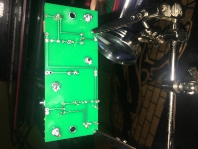
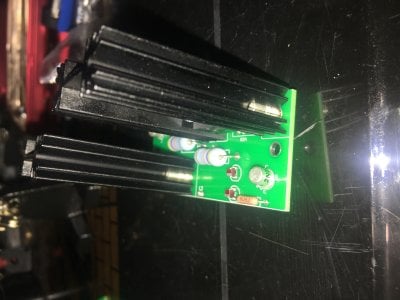
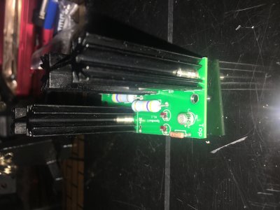
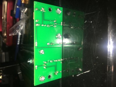
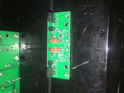
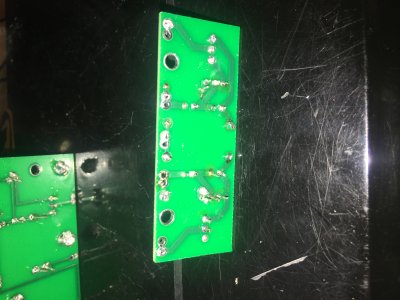
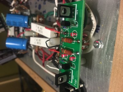
I spent a few days on and off building the Speedball, the first half went well with tests showing I didn't mess anything up, but now with the second bigger board installed the B part (D1 and D2) of the board doesn't light up, and one of the LEDs on the first smaller board, specifically D1 on the A side, doesn't light up. I need some help here, I'm not very good with this stuff
 
You'll need to perform the voltage checks in order for us to know what's going on.

Your thread title says that "only half of the tube heats up".  Which tube? Which half?  What's the indication that this is the case?
 
The low voltage at OB on the small board is odd.  Was that the voltage you got when you first put in the small PC board. 

The voltages at OA and OB on the small board shouldn't move at all when you put the big board in, so if you didn't have 46V at OB previously, then there's certainly cause for concern about how the big board was installed.

The high voltage at OB on the big PC board is unusual considering you are presenting very low voltage to the grid of the 6080 on that side and that there isn't really any high voltage present on the large PC board other than the portion that biases the LEDs.

My suggestion would be to remove the large PC board completely, then recheck the voltages on the small PC board. If the 48V pops back up to where you need it to be, then go over the manual very carefully and check the bottom of the large PC board for unsoldered connections or cold joints. The center leg on the TIP50 is one of those joints in particular that can soak up a lot of heat from your soldering iron, and a cold solder here can manifest some strange voltage problems.
 
Now things have gotten much worse, you now have no DC voltage at OA and the persistent low DC voltage at OB. 

I would suggest removing the small Speedball board as well, then putting back the resistors and checking that the stock build is still functional.
 
There is a very low hum when nothing is playing, turning up the volume makes it louder, but other than that, it works fine

1- 76.5
2- 156
3- 0
4- 156
5- 78.5
6- 0
7- 99.2
8- 0
9- 99.2
10- 0
 
Now that the boards are out, can you post photos of each.  Showing both the top and bottom may reveal where things went wrong. 

Do also check that the two red teflon wires were/are attached to T4.  If the one that feeds the big board got attached to T5, you'd end up with some problems. 
 
here you go
 

Attachments

  • Photo Apr 17, 6 48 21 PM.jpg
    Photo Apr 17, 6 48 21 PM.jpg
    1.8 MB · Views: 25
  • Photo Apr 17, 7 17 34 PM.jpg
    Photo Apr 17, 7 17 34 PM.jpg
    1.6 MB · Views: 15
  • Photo Apr 17, 7 17 44 PM.jpg
    Photo Apr 17, 7 17 44 PM.jpg
    1.6 MB · Views: 9
  • Photo Apr 17, 7 17 56 PM.jpg
    Photo Apr 17, 7 17 56 PM.jpg
    1.8 MB · Views: 14
  • Photo Apr 17, 7 18 18 PM.jpg
    Photo Apr 17, 7 18 18 PM.jpg
    2.2 MB · Views: 16
  • Photo Apr 17, 7 18 30 PM.jpg
    Photo Apr 17, 7 18 30 PM.jpg
    2 MB · Views: 17
Looks like you iron was not hot enough for the type of solder you used. Is this lead free solder?  Reflowing all the pads on the underside may very well fix things.
 
Standard 60/40 or 63/37 is supposed to be good with the iron set at around 650F. But around here we crank the iron up all the way (like 800F) and learn to hold the tip on the work just until the solder liquefies and flows into/around the solder pad and lead. Make sure you get the solder liquid enough for it to form a fillet shape in the joint.
 
To add to the wisdom of Doc B, the only components that you could possibly damage from excess soldering are the LEDs.  They don't need a ton of heat/solder for a proper joint, but feel free to cook the rest of the parts as much as you need to get the solder to flow into the board.

For each board hole, there's actually plating in the hole, so the solder will eventually flow down into these plated holes and that's how you'll end up with really good joints. 
 
Back
Top